Selecting the appropriate cooling fan for dry-type transformers represents a critical engineering decision that directly impacts transformer performance, reliability, and operational lifespan. Unlike oil-immersed transformers that rely on liquid dielectrics for heat dissipation, dry-type transformers depend entirely on air circulation to maintain safe operating temperatures. The cooling fan selection process requires understanding thermal load characteristics, airflow requirements, acoustic constraints, and installation environments. This comprehensive analysis examines the two dominant cooling fan technologies used in dry-type transformer applications—centrifugal fans and cross-flow fans—providing practical guidance for engineers and facility managers making this essential equipment decision.
The choice between centrifugal and cross-flow cooling fan configurations influences not only cooling effectiveness but also maintenance requirements, energy consumption, noise generation, and overall system costs throughout the transformer's operational life. Many engineers approach this decision by focusing solely on airflow volume specifications, yet optimal cooling fan selection demands consideration of pressure requirements, directional airflow patterns, space constraints, and integration with transformer winding geometry. This article provides a structured methodology for evaluating both cooling fan types against specific dry-type transformer requirements, helping you identify which technology best serves your application while avoiding common selection mistakes that compromise performance or create operational problems.
Understanding Cooling Requirements for Dry-Type Transformers
Heat Generation Characteristics in Dry-Type Transformers
Dry-type transformers generate heat through copper losses in windings and core losses in laminated steel, with the magnitude depending on load current, voltage rating, and efficiency class. The absence of oil cooling means all thermal energy must be transferred to surrounding air through convection and radiation. Core temperatures in standard dry-type transformers typically operate between 80°C and 150°C under rated load conditions, creating significant temperature differentials that drive natural convection. However, natural air circulation alone proves insufficient for most medium and high-capacity transformers, necessitating forced air cooling using strategically positioned fans. The cooling fan system must deliver sufficient airflow to maintain winding temperatures within insulation class limits—typically 105°C for Class A, 130°C for Class B, 155°C for Class F, and 180°C for Class H insulation systems.
Temperature rise calculations determine the minimum cooling capacity required from the fan system. Engineers must account for ambient temperature variations, altitude derating factors, and load profile patterns when sizing cooling equipment. A transformer operating in a 40°C ambient environment requires substantially more cooling capacity than one in a controlled 25°C facility. The cooling fan selection process begins with accurate thermal load assessment, typically expressed as heat rejection rate in kilowatts or BTU per hour. This thermal load directly translates to required airflow volume, measured in cubic feet per minute or cubic meters per hour, with the relationship governed by specific heat capacity of air and permissible temperature rise across the cooling system.
Airflow Pattern Requirements for Effective Cooling
The geometric configuration of transformer windings dictates optimal airflow patterns for heat removal. Most dry-type transformers utilize either disk-type or layer-type winding arrangements, each creating distinct cooling passages and thermal gradients. Effective cooling demands that air reaches the hottest internal regions—typically the center of winding heights and areas with maximum current density. Surface cooling alone leaves internal hot spots that accelerate insulation aging and increase failure risk. The cooling fan must generate airflow patterns that penetrate cooling ducts between winding layers, creating turbulent mixing that enhances convective heat transfer coefficients.
Directional airflow characteristics become particularly important in enclosed or semi-enclosed transformer installations where air must follow specific intake and exhaust paths. Centrifugal and cross-flow fans produce fundamentally different airflow patterns—centrifugal designs discharge air radially outward in a focused stream, while cross-flow configurations create broader, more uniform airflow across extended surfaces. The transformer enclosure design, ventilation grille placement, and available mounting locations all influence which airflow pattern delivers optimal cooling efficiency. Engineers must map airflow distribution using computational fluid dynamics analysis or empirical testing to verify that fan selection produces adequate air velocity throughout critical thermal zones without creating excessive pressure drop or flow recirculation zones.
Pressure Requirements and System Resistance
Cooling fan selection cannot rely on airflow volume specifications alone—static pressure capability determines whether the fan can actually deliver rated airflow against system resistance. Dry-type transformer cooling systems present resistance to airflow through multiple mechanisms: entrance and exit losses at ventilation openings, friction losses along cooling duct walls, directional change losses at bends, and obstruction losses around winding geometry. Total system resistance increases exponentially with airflow velocity, creating a performance curve that intersects with the fan's pressure-volume characteristic. The cooling fan must generate sufficient pressure at the required flow rate to overcome this cumulative resistance, with adequate margin for filter loading, grille obstruction, and aging degradation.
Centrifugal fans typically develop higher static pressure than cross-flow designs of comparable size, making them suitable for applications with restrictive airflow paths, extended ductwork, or high-efficiency filtration requirements. Cross-flow fans excel in low-resistance applications where uniform distribution matters more than pressure generation. Mismatched cooling fan selection—choosing a high-volume, low-pressure fan for a high-resistance application—results in dramatically reduced actual airflow despite impressive catalog specifications. Engineers should calculate system resistance curves using standard HVAC methodologies, accounting for all flow restrictions between ambient air intake and exhaust discharge, then select cooling fan models with operating points that intersect these curves at or above minimum required airflow volumes.
Centrifugal Cooling Fan Technology and Applications
Operating Principles and Design Characteristics
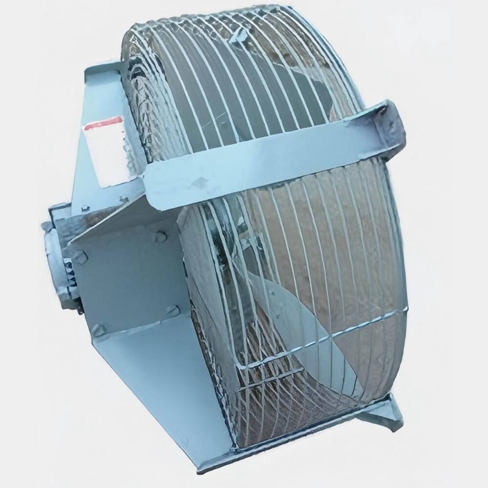
Centrifugal cooling fans employ rotating impellers with backward-curved, forward-curved, or radial blades that accelerate air outward through centrifugal force. Air enters axially through the impeller hub and discharges radially through a scroll housing that converts velocity pressure to static pressure. This fundamental operating principle enables centrifugal fans to develop substantial pressure head while maintaining compact axial dimensions. Backward-curved blade designs offer the highest efficiency, typically ranging from sixty to eighty percent, with non-overloading power characteristics that protect motors from damage during flow restriction. Forward-curved designs provide higher airflow at lower speeds but with reduced efficiency and potential motor overload characteristics under high-resistance conditions.
The scroll housing geometry critically influences centrifugal cooling fan performance and noise generation. Properly designed volutes gradually expand the flow area, recovering velocity pressure with minimal turbulence and achieving discharge velocities suitable for downstream ductwork connections. Centrifugal fans generate focused, directional airflow suitable for applications requiring air delivery through specific paths or against significant resistance. Their ability to maintain airflow under varying back-pressure conditions makes them reliable for transformer cooling applications where filter loading, grille blockage, or seasonal ambient variations alter system resistance. Modern centrifugal cooling fan designs incorporate aerodynamic refinements like curved blade entries, optimized blade angles, and streamlined housing contours that simultaneously improve efficiency and reduce acoustic emissions.
Advantages for Dry-Type Transformer Cooling
Centrifugal cooling fans provide several distinct advantages for dry-type transformer applications, particularly in challenging installation environments. Their superior pressure generation capability enables effective cooling in configurations with restricted ventilation openings, extended air delivery distances, or high-efficiency particulate filtration. Industrial facilities with contaminated ambient air often require protective filters that create substantial pressure drop—centrifugal fans maintain adequate airflow despite this resistance where other technologies would fail. The focused discharge pattern allows precise air delivery to specific transformer regions, optimizing cooling effectiveness when combined with properly designed ductwork or plenum chambers that distribute airflow across winding surfaces.
Space efficiency represents another significant advantage, as centrifugal designs achieve high airflow and pressure in compact radial packages that fit within tight installation footprints. This dimensional advantage proves valuable in retrofit applications where existing transformer enclosures limit cooling fan mounting options. Centrifugal cooling fans also demonstrate excellent performance stability across wide operating ranges, maintaining predictable airflow even as system resistance varies due to filter loading or seasonal temperature changes. Their robust construction and sealed bearing arrangements provide reliable operation in harsh environments with elevated temperatures, humidity, or vibration—conditions commonly encountered in industrial transformer installations. The directional exhaust facilitates heat rejection away from sensitive equipment or into dedicated ventilation systems.
Limitations and Design Considerations
Despite their advantages, centrifugal cooling fans present certain limitations that influence application suitability. Their focused airflow pattern, while advantageous for directed delivery, creates non-uniform velocity distributions that may leave some transformer surfaces inadequately cooled without supplementary air distribution systems. Achieving uniform cooling across wide transformer faces typically requires multiple centrifugal fan installations or elaborate ductwork that adds cost and complexity. The rotating impeller and scroll housing geometry generate characteristic tonal noise components, particularly at blade-pass frequencies, that may exceed acoustic limits in sound-sensitive installations despite overall noise levels appearing acceptable on A-weighted measurements.
Centrifugal cooling fan maintenance requirements demand accessibility for periodic inspection and bearing lubrication, with more complex disassembly procedures compared to simpler fan configurations. The radial discharge orientation requires careful integration with transformer enclosure design to avoid air recirculation or short-circuiting that bypasses critical cooling zones. Installation orientation matters significantly—mounting position affects bearing loading and performance, with some centrifugal designs specified only for specific orientations. Engineers must also consider starting torque requirements, as centrifugal fans with high inertia impellers demand motors with adequate locked-rotor characteristics. Power consumption tends toward the higher end of cooling fan options, particularly in forward-curved designs, impacting long-term operating costs in continuous-duty transformer cooling applications.
Cross-Flow Cooling Fan Technology and Applications
Operating Principles and Design Characteristics
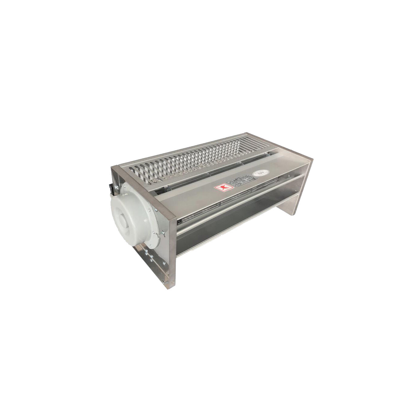
Cross-flow cooling fans utilize elongated cylindrical impellers with forward-curved blades arranged around the circumference, creating airflow that enters one side of the impeller and exits the opposite side after flowing across the blade array. Unlike centrifugal designs where air turns ninety degrees, cross-flow configurations maintain roughly tangential flow direction while increasing velocity and pressure through blade action. The resulting airflow pattern emerges as a wide, uniform sheet along the impeller length—a characteristic that provides distinct advantages for cooling extended surfaces like transformer windings. Cross-flow impellers typically span the full width of the transformer to be cooled, producing remarkably uniform airflow distribution without requiring complex ductwork or multiple fan installations.
The aerodynamic efficiency of cross-flow cooling fans generally ranges between forty and sixty percent, lower than optimized centrifugal designs but acceptable for many cooling applications where uniform distribution and compact mounting outweigh pure efficiency concerns. These fans excel at moving large volumes of air at relatively low pressures, with performance characteristics well-suited to low-resistance cooling paths common in open or semi-enclosed transformer configurations. The blade design and housing geometry significantly influence performance, with modern cross-flow fans incorporating optimized blade angles, turbulence-reducing housings, and carefully shaped inlet and outlet regions that minimize losses while maintaining quiet operation. Their slim rectangular profile enables mounting configurations that would be impossible with bulkier centrifugal alternatives.
Advantages for Dry-Type Transformer Cooling
Cross-flow cooling fans deliver exceptional airflow uniformity across wide surfaces, making them ideal for cooling applications where even temperature distribution matters critically. A single cross-flow fan spanning a transformer's width provides more uniform cooling than multiple point-source centrifugal fans, eliminating hot spots and optimizing overall thermal performance. This uniform distribution characteristic proves particularly valuable for large power transformers with extensive winding surfaces where maintaining consistent temperatures across all regions extends insulation life and improves reliability. The wide, gentle airflow pattern also reduces local velocity peaks that could create acoustic noise through interaction with transformer structures or generate excessive pressure loads on delicate insulation materials.
Installation flexibility represents another compelling advantage, as cross-flow cooling fan configurations adapt easily to diverse mounting arrangements. Their elongated rectangular form factor fits naturally along transformer sides or beneath units, utilizing space that would otherwise remain unused. The tangential airflow direction simplifies integration with transformer enclosures, requiring only inlet and outlet openings without complex turning vanes or distribution plenums. Cross-flow fans typically generate lower acoustic emissions than centrifugal equivalents at comparable airflow rates, with less tonal noise content and more benign frequency spectra that subjectively sound quieter even at similar decibel levels. This acoustic advantage proves valuable in commercial buildings, healthcare facilities, or other sound-sensitive environments where transformer cooling fan noise could create complaints or regulatory issues.
Limitations and Design Considerations
Cross-flow cooling fans demonstrate limited pressure-generating capability compared to centrifugal alternatives, restricting their application to systems with minimal airflow resistance. Installations requiring significant ductwork lengths, high-efficiency filtration, or multiple directional changes typically exceed cross-flow pressure capabilities, resulting in inadequate airflow delivery. The uniform discharge pattern, while advantageous for surface cooling, provides less control over airflow direction and may prove difficult to integrate with transformer designs requiring focused air delivery to specific hot-spot regions. Engineers cannot easily adapt cross-flow installations to direct cooling where needed most, unlike centrifugal systems where ductwork redirects airflow precisely.
The elongated impeller design creates structural challenges, with longer spans requiring careful bearing support to prevent deflection and vibration. Bearing arrangements at both impeller ends increase parts count and potential maintenance requirements compared to single-bearing centrifugal designs. Cross-flow cooling fan performance shows greater sensitivity to installation precision—misalignment between impeller and housing creates significant efficiency losses and noise increases. The low operating pressure also means that external factors like wind pressure or building HVAC interactions can disrupt airflow patterns more readily than with higher-pressure centrifugal systems. In outdoor installations or areas with variable pressure conditions, cross-flow fans may experience unstable operation or reverse flow situations that compromise cooling effectiveness.
Comparative Selection Framework for Transformer Cooling
Application Requirements Analysis
Selecting between centrifugal and cross-flow cooling fan technologies begins with systematic analysis of specific application requirements. Engineers should document transformer thermal load, required airflow volume, available mounting space, acoustic limits, environmental conditions, and maintenance accessibility constraints. Thermal load assessment determines minimum cooling capacity, while pressure drop calculations through transformer cooling passages establish whether low-pressure cross-flow or higher-pressure centrifugal technology better suits the application. Transformer physical dimensions influence cooling fan sizing—wide, flat configurations favor cross-flow uniformity, while compact vertical designs may accommodate centrifugal arrangements more naturally.
Environmental factors significantly impact cooling fan selection decisions. Installations in contaminated atmospheres requiring inlet filtration typically necessitate centrifugal fans capable of overcoming filter pressure drop. Outdoor locations exposed to wind, rain, or temperature extremes demand robust fan construction and weather-resistant motor specifications regardless of technology choice. Altitude affects cooling performance through reduced air density, requiring airflow volume increases that may push cross-flow fans beyond practical limits while remaining within centrifugal capabilities. Acoustic requirements deserve careful attention, as noise specifications may eliminate certain fan types or mandate sound attenuation accessories that alter system pressure characteristics. Engineers should create weighted decision matrices that score each cooling fan option against all relevant criteria rather than selecting based on single-factor optimization.
Performance Trade-offs and Decision Criteria
Direct performance comparison between centrifugal and cross-flow cooling fans reveals fundamental trade-offs that guide selection logic. Centrifugal technology offers superior pressure capability, efficiency, and reliability in demanding applications but sacrifices uniformity and requires more complex installation integration. Cross-flow technology delivers unmatched distribution uniformity and installation simplicity while limiting maximum achievable pressure and showing sensitivity to system variations. The optimal choice depends on which performance attributes matter most for specific transformer cooling requirements. High-capacity transformers with substantial thermal loads and restricted ventilation generally favor centrifugal fans, while medium-capacity units in open installations often benefit from cross-flow uniformity.
Economic analysis should encompass total lifecycle costs rather than initial purchase price alone. Higher-efficiency centrifugal cooling fans cost more initially but consume less energy over decades of continuous operation, potentially recovering premium prices through reduced utility bills. Maintenance accessibility and parts availability influence long-term cost of ownership—simpler designs with readily available components reduce downtime expenses and support costs. Acoustic performance may carry economic implications beyond mere compliance, as quieter cooling fan systems enable transformer placement closer to occupied spaces, reducing expensive cable runs and voltage drop concerns. Engineers should model total cost of ownership across expected transformer lifespan, incorporating energy costs, maintenance expenses, and operational value factors into comprehensive economic comparisons.
Hybrid and Alternative Configurations
Some dry-type transformer cooling applications benefit from hybrid approaches combining multiple cooling fan technologies or alternative configurations optimized for specific situations. Large power transformers may employ centrifugal fans for primary cooling supplemented by cross-flow fans for localized hot-spot management, leveraging strengths of both technologies. Staged cooling fan control systems activate different fan types based on load conditions, operating efficient low-pressure fans during light loads and engaging high-capacity centrifugal fans only when thermal demands require maximum cooling. This approach optimizes energy consumption while maintaining adequate cooling across full load ranges.
Alternative cooling fan technologies merit consideration in specialized applications. Axial fans provide high airflow at very low pressure in completely unrestricted installations, though their characteristics rarely suit typical dry-type transformer cooling requirements. Variable-speed cooling fan systems using inverter drives enable continuous capacity modulation, improving efficiency and reducing acoustic emissions during light-load operation regardless of underlying fan technology. Heat pipe or thermosiphon-assisted cooling supplements forced convection, potentially reducing cooling fan capacity requirements. Engineers should remain open to innovative solutions rather than defaulting to conventional approaches, particularly for challenging applications where standard centrifugal or cross-flow options present compromises. Emerging technologies like electronically commutated motors, aerodynamic blade optimizations, and smart control algorithms continue improving cooling fan performance across all technology types.
Implementation Best Practices and Optimization Strategies
Installation Design and Integration
Proper cooling fan installation critically affects actual performance regardless of equipment selection quality. Transformer enclosures must provide adequate inlet and outlet ventilation areas with minimal flow restriction—generally sizing openings for maximum air velocities below 500 feet per minute to limit pressure losses. Inlet screens or grilles should use expanded metal or large-pitch designs rather than fine meshes that create excessive resistance. The cooling fan discharge must connect smoothly to transformer cooling passages without abrupt transitions that generate turbulence and pressure loss. When using centrifugal fans, gradual enlargement ductwork between fan outlet and transformer inlet optimizes pressure recovery and distribution.
Cross-flow cooling fan installations benefit from careful attention to clearances between impeller and housing surfaces, as gaps create bypass flows that dramatically reduce efficiency. Mounting brackets must maintain precise alignment throughout thermal cycling and vibration exposure. Both fan types require vibration isolation when mounted to resonant structures, using flexible connectors or isolation pads that prevent vibration transmission while maintaining airflow integrity. Electrical installation should follow manufacturer specifications regarding motor protection, circuit sizing, and control integration. Temperature-based fan control systems should employ redundant sensors monitoring multiple transformer locations rather than single-point measurements that might miss localized overheating. Proper grounding and electromagnetic compatibility practices prevent interference with transformer protection relays or monitoring equipment.
Performance Verification and Commissioning
Commissioning procedures should verify that installed cooling fan systems deliver design performance under actual operating conditions. Airflow measurement using traverse measurements across cooling passages confirms actual flow rates against design specifications. Temperature mapping during loaded operation identifies any hot spots or inadequate cooling zones requiring airflow redistribution or supplementary cooling. Acoustic surveys at specified measurement locations verify compliance with noise limits and identify any unexpected tonal components indicating installation problems. Vibration analysis detects potential bearing issues, unbalance conditions, or resonance problems before they progress to failure.
Long-term monitoring systems track cooling fan performance trends, detecting gradual degradation that signals maintenance needs before cooling inadequacy threatens transformer health. Motor current monitoring identifies bearing wear or blade fouling through increased power consumption. Temperature trend analysis reveals whether cooling capacity maintains design margins or shows concerning increases suggesting filter loading, fan degradation, or transformer cooling passage blockage. Periodic thermal imaging inspections visualize temperature distributions, confirming continued cooling uniformity. Establishing baseline performance data during commissioning enables meaningful comparison with ongoing measurements, supporting predictive maintenance programs that optimize reliability while minimizing unnecessary interventions.
Maintenance Planning and Reliability Optimization
Preventive maintenance programs substantially extend cooling fan service life and maintain performance reliability. Bearing lubrication according to manufacturer schedules prevents premature wear, with sealed bearing designs reducing maintenance frequency compared to open bearings. Periodic impeller cleaning removes accumulated dust and debris that reduces airflow and increases imbalance. Filter replacement or cleaning maintains system pressure characteristics within design ranges, preventing gradual airflow degradation. Motor inspection includes insulation resistance testing, connection tightness verification, and thermal survey to detect developing problems.
Spare parts inventory should include critical components with significant lead times, particularly specialized motors or impellers for obsolete cooling fan models. Bearing replacements, motor capacitors, and common electrical components enable rapid repair response. Documentation of original specifications, installation details, and modification history supports future troubleshooting and replacement decisions. As cooling fans approach end of service life, proactive replacement during scheduled outages prevents unexpected failures that could force transformer derating or emergency shutdowns. Modern cooling fan technologies offer improved efficiency and reliability compared to older designs, making strategic upgrades economically attractive even before failure occurs.
FAQ
What airflow volume should I specify for my dry-type transformer cooling fan system?
Required airflow volume depends on transformer thermal load and permissible temperature rise. A general guideline suggests approximately 150 to 250 cubic feet per minute per kilowatt of transformer losses for forced-air cooling, though specific requirements vary based on transformer design, altitude, ambient temperature, and desired temperature margins. Consult transformer manufacturer thermal specifications to determine heat rejection requirements, then calculate airflow using the relationship accounting for air density and temperature differential. Always include safety margins of 15 to 25 percent above calculated minimums to accommodate filter loading, aging degradation, and unexpected load increases.
Can I replace centrifugal cooling fans with cross-flow fans on an existing transformer installation?
Replacement feasibility depends on system pressure requirements and available mounting space. Cross-flow fans generally develop lower pressure than centrifugal units, so direct replacement works only if the existing system operates with minimal resistance and the original centrifugal fans were significantly oversized for pressure capability. You must verify that replacement cross-flow fans can overcome actual system pressure drop while delivering required airflow volume. Physical mounting also differs substantially between technologies—cross-flow units require elongated mounting spaces while centrifugal fans need radial discharge clearance. Successful replacement typically requires engineering analysis including pressure drop calculations and potentially modifications to transformer ventilation arrangements.
How do I reduce cooling fan noise in noise-sensitive transformer installations?
Multiple strategies reduce cooling fan acoustic emissions. Select fans specifically designed for quiet operation with aerodynamically optimized blades and housings that minimize turbulence. Operate fans at lower speeds using oversized units or variable-speed drives, as acoustic power decreases dramatically with reduced rotational speed. Install acoustic enclosures around fan assemblies using sound-absorbing materials, though ensure adequate ventilation to prevent recirculation. Use flexible duct connections and vibration isolators to prevent structure-borne noise transmission. Cross-flow cooling fans generally produce less objectionable noise than centrifugal types at equivalent airflow. For existing installations, add inlet silencers or outlet attenuators designed for HVAC applications, verifying that added resistance does not compromise cooling performance.
What maintenance intervals do cooling fans require in continuous transformer cooling service?
Maintenance frequency depends on operating environment and cooling fan design. Clean industrial environments with sealed-bearing fans may require only annual inspections with bearing lubrication every two to three years. Contaminated or outdoor installations need quarterly inspections with more frequent filter changes and cleaning. Check motor current, vibration levels, and bearing temperatures during each inspection to detect developing problems. Plan bearing replacement every five to seven years for continuously operating units regardless of apparent condition, as bearing lubrication degrades over time even without obvious symptoms. Major overhauls including motor rewinding and complete impeller replacement typically occur at ten to fifteen year intervals. Establish site-specific schedules based on actual operating experience and manufacturer recommendations rather than applying generic intervals.
Table of Contents
- Understanding Cooling Requirements for Dry-Type Transformers
- Centrifugal Cooling Fan Technology and Applications
- Cross-Flow Cooling Fan Technology and Applications
- Comparative Selection Framework for Transformer Cooling
- Implementation Best Practices and Optimization Strategies
-
FAQ
- What airflow volume should I specify for my dry-type transformer cooling fan system?
- Can I replace centrifugal cooling fans with cross-flow fans on an existing transformer installation?
- How do I reduce cooling fan noise in noise-sensitive transformer installations?
- What maintenance intervals do cooling fans require in continuous transformer cooling service?