Selecting the right cooling fan for dry-type transformers is a critical engineering decision that directly impacts operational efficiency, thermal management performance, and equipment longevity. Dry-type transformers rely entirely on forced air cooling to dissipate heat generated during operation, making the fan selection process a cornerstone of reliable electrical infrastructure design. The choice between centrifugal fans and cross-flow fans depends on multiple technical variables including transformer winding configuration, ambient operating conditions, enclosure design constraints, and noise level requirements. Understanding how to match these fan technologies to specific transformer characteristics ensures optimal heat dissipation while maintaining energy efficiency and compliance with industrial standards.
Proper fan matching begins with a thorough analysis of the transformer's thermal profile and cooling requirements, factoring in rated capacity, temperature rise class, and installation environment. This article provides a systematic approach to evaluating airflow characteristics, pressure requirements, and acoustic performance to determine whether centrifugal or cross-flow fan technology best suits your dry-type transformer application. By following these engineering principles and practical guidelines, electrical system designers and facility managers can make informed decisions that balance thermal performance with operational costs and regulatory compliance.
Understanding Transformer Cooling Requirements and Fan Selection Fundamentals
Heat Generation Patterns in Dry-Type Transformers
Dry-type transformers generate heat primarily through two mechanisms: core losses from magnetic hysteresis and eddy currents, and copper losses from winding resistance. The total heat load varies with transformer capacity, typically ranging from several hundred watts for small units to tens of kilowatts for large distribution transformers. Heat distribution is not uniform throughout the transformer body, with winding regions experiencing higher thermal concentrations than core sections. Understanding these heat generation patterns is essential when determining the airflow volume and distribution characteristics required from cooling fans.
Temperature rise class designations such as Class F or Class H indicate the permissible temperature increase above ambient conditions during full-load operation. A Class F transformer with 100K temperature rise requires cooling systems capable of maintaining winding temperatures within specified limits under continuous operation. The cooling fan system must be designed to handle not only steady-state thermal loads but also transient thermal spikes during overload conditions. Effective fan selection accounts for these dynamic thermal behaviors to prevent premature insulation degradation and ensure transformer service life expectations are met.
Airflow Volume Calculation Methods
Calculating required airflow volume begins with determining the total heat dissipation load in watts or kilowatts. The basic formula relates heat removal capacity to air volume flow rate and temperature differential across the transformer. For forced air cooling systems, the required airflow in cubic meters per hour can be calculated using the relationship between heat load, specific heat capacity of air, air density, and allowable temperature rise. Conservative engineering practice typically includes a safety margin of fifteen to twenty percent above calculated values to account for airflow resistance, filter contamination over time, and variations in ambient conditions.
Beyond total volume requirements, airflow distribution characteristics significantly impact cooling effectiveness. Uniform air distribution across all winding surfaces prevents localized hot spots that could compromise insulation integrity. The cross-flow fan configuration excels at providing longitudinal airflow patterns that sweep across extended surfaces, making it particularly suitable for transformers with horizontal winding arrangements or elongated enclosure geometries. Centrifugal fans typically deliver higher static pressures, allowing them to overcome greater resistance in ducted configurations or when forcing air through densely packed winding assemblies.
Pressure Drop Considerations in Transformer Enclosures
Static pressure requirements depend heavily on the transformer enclosure design and air path complexity. Open ventilated transformers with unrestricted inlet and outlet grilles present minimal airflow resistance, typically requiring only fifty to one hundred pascals of static pressure. Enclosed transformers with air filters, internal baffles, or extended ducting may require several hundred pascals of pressure to achieve necessary airflow rates. Accurate pressure drop calculation must account for all airflow restrictions including filter media, grille resistance, sudden expansions or contractions in air passages, and friction losses along duct surfaces.
Centrifugal fans generate higher static pressures compared to cross-flow fans of similar size, making them preferred choices for applications with significant airflow resistance. However, a cross-flow fan can effectively serve low-resistance applications where uniform airflow distribution across extended surfaces is more critical than overcoming high static pressure. When matching fans to transformer cooling requirements, engineers must plot the fan performance curve against the system resistance curve to identify the operating point. This intersection determines actual delivered airflow and power consumption, ensuring the selected fan meets cooling requirements without excessive energy use or noise generation.
Comparing Centrifugal and Cross-Flow Fan Technologies for Transformer Cooling
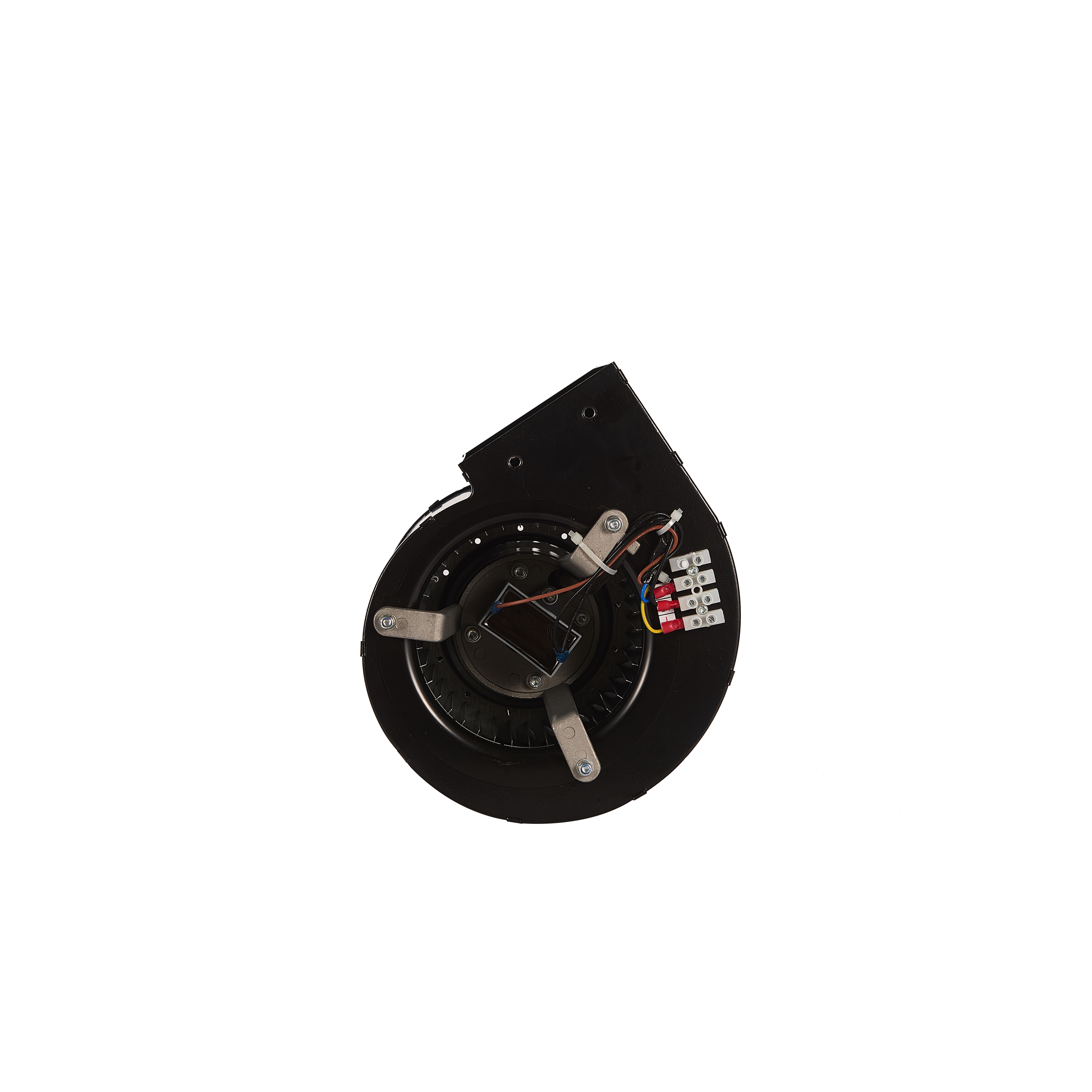
Centrifugal Fan Operating Principles and Performance Characteristics
Centrifugal fans operate by drawing air into the impeller along the axis of rotation and discharging it radially outward through the scroll housing. This design generates high static pressure capability, making centrifugal fans effective for applications requiring air movement through restricted passages or against significant back pressure. Forward-curved, backward-curved, and radial blade designs offer different performance profiles, with backward-curved impellers generally providing higher efficiency and better part-load performance. Centrifugal fans can achieve static pressures exceeding five hundred pascals while maintaining reasonable energy efficiency when properly sized.
In transformer cooling applications, centrifugal fans are typically mounted at enclosure ends or sides, directing concentrated airflow through ducting or directing vanes toward critical heat-generating components. The compact footprint of centrifugal fans allows integration into space-constrained installations where mounting area is limited. However, the point-source discharge pattern of centrifugal fans may require additional air distribution systems such as plenums or baffle arrangements to achieve uniform cooling across transformer surfaces. Noise generation tends to be directional with centrifugal fans, concentrated in the discharge direction, which can be advantageous when positioning equipment away from noise-sensitive areas.
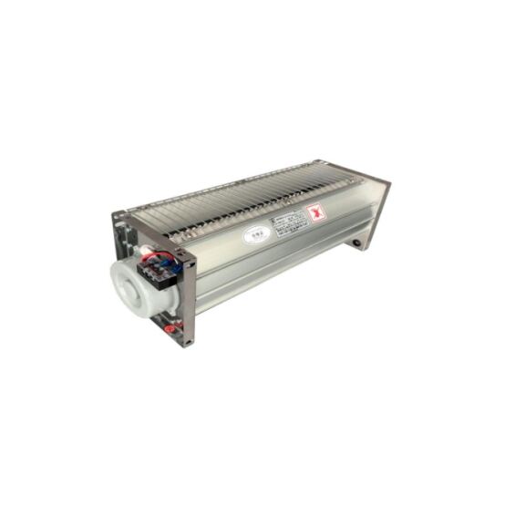
Cross-Flow Fan Design Advantages for Linear Cooling Applications
The cross-flow fan employs a distinctive cylindrical impeller with forward-curved blades that draw air in along one side of the cylinder and discharge it along the opposite side. This configuration creates an elongated discharge pattern perpendicular to the impeller axis, producing a uniform airflow curtain across the entire length of the fan assembly. For dry-type transformers with horizontal winding configurations or rectangular enclosures, cross-flow fan technology provides inherently superior airflow distribution without requiring complex ducting or baffle systems.
Cross-flow fan installations typically span the full length or width of the transformer enclosure, mounting parallel to the winding surfaces requiring cooling. This arrangement enables direct surface cooling with minimal dead zones or poorly ventilated areas. The relatively low static pressure capability of cross-flow fans suits applications with open ventilation paths and minimal airflow restrictions. Installation simplicity represents another advantage, as cross-flow fans can be integrated directly into enclosure panels without extensive modification to transformer housing structures. The distributed airflow pattern also contributes to more uniform acoustic signatures with less directional noise concentration compared to centrifugal configurations.
Energy Efficiency and Power Consumption Analysis
Energy consumption during continuous transformer operation makes fan efficiency a significant economic consideration over equipment service life. Centrifugal fans with backward-curved impellers can achieve efficiencies between sixty and seventy-five percent at design operating points, though efficiency drops considerably at off-design conditions. Cross-flow fan efficiency typically ranges from forty to sixty percent due to inherent aerodynamic characteristics and recirculation losses within the impeller. However, the ability of cross-flow fans to provide effective cooling without auxiliary ducting systems may offset lower inherent efficiency in some applications.
Total system efficiency must account for both fan power consumption and cooling effectiveness in maintaining transformer operating temperatures. An oversized high-efficiency centrifugal fan operating far from its design point may consume more energy than a properly matched cross-flow fan with lower peak efficiency. Variable speed control capabilities enable both fan types to modulate airflow based on actual thermal loads, significantly reducing energy consumption during partial load operation. When transformers operate below rated capacity for extended periods, variable speed fan control can reduce cooling system energy use by fifty percent or more while maintaining adequate thermal management.
Application-Specific Matching Criteria for Different Transformer Configurations
Indoor Substation Transformers with Space Constraints
Indoor substation environments typically impose strict spatial limitations on transformer installations and auxiliary cooling equipment. Transformers installed in equipment rooms, basement vaults, or tight electrical closets require compact cooling solutions that maximize thermal performance within minimal footprints. Centrifugal fans excel in these space-constrained applications due to their high pressure capability in compact housings, allowing effective cooling even when airflow paths include multiple bends or restrictions. Wall-mounted or ceiling-mounted centrifugal fan installations can draw cooling air from remote locations and direct it precisely where needed.
Acoustic considerations become paramount in indoor installations, particularly when transformer rooms share walls with occupied spaces or sensitive equipment areas. The cross-flow fan configuration offers acoustic advantages in some indoor applications due to its distributed airflow pattern and lower peak velocities compared to the concentrated discharge of centrifugal fans. Sound attenuation measures such as acoustically lined enclosures or vibration isolation mounts may be necessary regardless of fan type. When matching fans to indoor transformers, engineers must balance thermal performance requirements against noise limits specified in building codes or facility operational standards.
Outdoor Pad-Mounted and Pole-Mounted Transformer Applications
Outdoor transformer installations face environmental challenges including temperature extremes, precipitation exposure, airborne contaminants, and potential wildlife intrusion. Cooling fans for outdoor applications require weather-resistant construction with appropriate ingress protection ratings, typically IP54 or higher to prevent water and dust infiltration. Centrifugal fans with sealed motor housings and corrosion-resistant materials provide robust performance in harsh outdoor environments. The concentrated airflow discharge of centrifugal fans can be oriented downward or away from prevailing weather directions to minimize direct exposure to precipitation.
Cross-flow fan systems for outdoor transformers must incorporate protective measures such as rain hoods, insect screens, and drain provisions to prevent water accumulation within the elongated fan housing. The horizontal orientation typical of cross-flow fan installations may require additional weather protection compared to vertically oriented centrifugal configurations. However, the distributed cooling pattern of cross-flow fans can be advantageous for pole-mounted transformers where mounting space is limited and uniform cooling of vertically oriented windings is required. Material selection for outdoor applications should prioritize aluminum or stainless steel construction with powder-coated or anodized finishes to ensure long-term durability in corrosive environments.
High-Temperature and Harsh Industrial Environment Considerations
Industrial facilities such as steel mills, chemical plants, and heavy manufacturing operations subject transformers and cooling equipment to extreme ambient temperatures, corrosive atmospheres, and high levels of airborne particulates. When ambient temperatures regularly exceed forty degrees Celsius, fan motor specifications must include appropriate thermal class ratings and potentially special cooling provisions for the fan motors themselves. Cross-flow fan motors mounted within the airflow stream benefit from continuous cooling during operation, whereas centrifugal fan motors may require separate ventilation in high-temperature environments.
Particulate contamination presents challenges for both fan technologies, necessitating filtration systems that balance air quality against pressure drop penalties. Centrifugal fans with backward-curved impellers demonstrate better resistance to particulate buildup compared to forward-curved designs, as the blade geometry promotes self-cleaning action. Cross-flow fan impellers can accumulate debris along their cylindrical length, requiring accessible designs that facilitate periodic cleaning and maintenance. In corrosive atmospheres containing chemical vapors or salt spray, both centrifugal and cross-flow fan materials must resist chemical attack through appropriate alloy selection or protective coatings. Matching fans to harsh environment transformers requires careful evaluation of total cost of ownership including maintenance frequency and replacement component availability.
Practical Implementation Guidelines and Performance Optimization
Sizing and Specification Development Process
Developing accurate fan specifications begins with comprehensive transformer thermal data including rated capacity, impedance, core and copper losses, and temperature rise class. This information enables calculation of total heat dissipation requirements under various load conditions. Engineers should request detailed transformer enclosure drawings showing internal geometry, airflow path configurations, and available mounting locations for cooling equipment. These physical constraints significantly influence whether centrifugal or cross-flow fan technology provides the most practical solution for a specific installation.
Performance specifications must address multiple operating scenarios including continuous full-load operation, temporary overload conditions, and reduced-load operation during off-peak periods. Fan selection should ensure adequate cooling capacity at maximum anticipated ambient temperature with appropriate safety margins for future load growth or unanticipated operating conditions. When specifying cross-flow fan systems, particular attention to discharge length and uniformity helps ensure complete coverage of transformer cooling surfaces. Centrifugal fan specifications should clearly define static pressure requirements based on detailed system resistance calculations including all filters, ducting, and grille elements in the airflow path.
Installation Best Practices and Airflow Optimization
Proper installation technique significantly impacts cooling system effectiveness regardless of fan technology selection. Centrifugal fan installations require attention to inlet conditions, as restricted or turbulent inlet airflow dramatically reduces fan performance and increases noise generation. Maintaining straight, unrestricted inlet ducting for at least one duct diameter improves centrifugal fan efficiency and reduces turbulence-related noise. Discharge connections should avoid sharp bends immediately downstream of the fan outlet, as these create unnecessary pressure losses and reduce delivered airflow.
Cross-flow fan installations benefit from careful attention to discharge clearance and outlet geometry. Mounting the cross-flow fan with adequate clearance from transformer surfaces allows the characteristic airflow curtain to develop fully before impinging on heat exchange surfaces. Internal baffles or air guides can enhance airflow distribution in complex enclosure geometries, ensuring that cooling air reaches all critical areas rather than short-circuiting through paths of least resistance. Both centrifugal and cross-flow fan systems should include provisions for periodic inspection and maintenance access, as accumulated dust and debris on impeller surfaces progressively degrades performance and increases energy consumption over time.
Control Strategies and Temperature Monitoring Integration
Modern transformer cooling systems increasingly incorporate intelligent control strategies that modulate fan operation based on actual thermal conditions rather than continuous full-speed operation. Temperature sensors embedded in transformer windings provide real-time thermal data to control systems that adjust fan speed to match instantaneous cooling requirements. Variable frequency drives enable both centrifugal and cross-flow fan speed modulation, reducing energy consumption during partial load conditions while maintaining thermal protection during peak demand periods. Multi-stage control systems may activate different quantities of fans in response to load levels, providing economical cooling at light loads while ensuring adequate capacity during maximum demand.
Integration with building management systems or substation automation platforms enables remote monitoring of fan performance and early detection of degraded operation. Monitoring parameters such as motor current, vibration levels, and bearing temperatures provides advance warning of impending failures, allowing scheduled maintenance rather than emergency repairs. When matching cross-flow fan systems to transformer cooling requirements, consideration should be given to control system compatibility and communication protocols. Sophisticated control strategies optimize the balance between thermal management performance and operating costs while extending both transformer and cooling system service life through reduced thermal stress and mechanical wear.
FAQ
What is the primary difference between centrifugal and cross-flow fans for transformer cooling?
The primary difference lies in airflow pattern and pressure capability. Centrifugal fans generate concentrated, high-pressure airflow discharged radially from a compact housing, making them suitable for applications with significant airflow resistance or ducted configurations. Cross-flow fans produce elongated, uniform airflow curtains along their entire length with lower pressure capability, ideal for direct surface cooling of transformers with horizontal winding arrangements. Centrifugal fans excel when space is limited and high static pressure is required, while cross-flow fans provide superior airflow distribution across extended surfaces in low-resistance applications.
How do I calculate the required airflow volume for my dry-type transformer?
Calculate required airflow by dividing total heat dissipation in watts by the product of air density, specific heat capacity, and allowable temperature rise. For practical purposes, transformers typically require approximately one hundred to one hundred fifty cubic meters per hour of airflow per kilowatt of heat dissipation, depending on enclosure design and ambient conditions. Add a safety margin of fifteen to twenty percent to account for filter resistance, aging effects, and operational variations. Always verify calculations against transformer manufacturer recommendations and consider both steady-state and transient thermal loading conditions when determining final fan capacity requirements.
Can cross-flow fans handle outdoor transformer installations effectively?
Cross-flow fans can effectively serve outdoor transformer installations when properly specified with appropriate weather protection and environmental ratings. The elongated housing design requires protective measures against precipitation infiltration, including rain hoods, drain provisions, and sealed motor enclosures with minimum IP54 ingress protection. Material selection should emphasize corrosion-resistant construction such as aluminum or stainless steel with appropriate surface treatments. While centrifugal fans may offer simpler weather protection in some outdoor configurations, cross-flow fans remain viable when their airflow distribution advantages justify the additional weatherproofing measures required for reliable outdoor operation.
What maintenance requirements should I expect for transformer cooling fans?
Routine maintenance for both centrifugal and cross-flow fans includes periodic inspection and cleaning of impeller surfaces to remove accumulated dust and debris that reduces airflow and increases power consumption. Motor bearings require lubrication or replacement according to manufacturer schedules, typically annually for continuous-duty applications. Air filters in the intake path need replacement every three to six months depending on environmental conditions and particulate loading. Monitor vibration levels and motor current draw as indicators of mechanical wear or impeller imbalance requiring corrective action. Cross-flow fan maintenance may require slightly more effort due to the elongated impeller design, but accessibility provisions in the installation can minimize downtime during servicing activities.
Table of Contents
- Understanding Transformer Cooling Requirements and Fan Selection Fundamentals
- Comparing Centrifugal and Cross-Flow Fan Technologies for Transformer Cooling
- Application-Specific Matching Criteria for Different Transformer Configurations
- Practical Implementation Guidelines and Performance Optimization
-
FAQ
- What is the primary difference between centrifugal and cross-flow fans for transformer cooling?
- How do I calculate the required airflow volume for my dry-type transformer?
- Can cross-flow fans handle outdoor transformer installations effectively?
- What maintenance requirements should I expect for transformer cooling fans?