 EN
EN
How They Work: The Operating Principles of Dry-Type Transformers and Cooling Fans
Published by: Shanghai Angeda
Introduction
When you buy power distribution equipment, you are not just buying metal, copper, and resin — you are buying a controlled flow of energy that must keep running safely for decades. Understanding how a dry-type transformer and its cooling fan actually work is not academic theory: it shapes your specification, your maintenance plan, and your expectations of service life.
This article explains, in plain engineering language, the operating principles behind our two product lines — dry-type transformers and dry-type cooling fans — and how they work together as one system.
Part 1: How a Dry-Type Transformer Works
The Core Idea: Electromagnetic Induction
Every transformer, dry-type or oil-filled, works on one principle discovered by Michael Faraday in 1831: a changing magnetic field induces a voltage in a conductor.
Inside the transformer, alternating current (AC) flows through the primary winding, creating an alternating magnetic field around it. That field is channeled through the iron core and links the secondary winding. Because the field is continuously rising and falling with the AC cycle, it induces a voltage in the secondary winding — no mechanical connection, no moving parts, just pure electromagnetic coupling.
The magic of the transformer is that the two windings can have different numbers of turns, and the voltage ratio follows the turn ratio exactly:
V₁ / V₂ = N₁ / N₂
- More turns on the secondary than the primary → voltage is stepped
up.
- Fewer turns on the secondary → voltage is stepped
down
(the common case for distribution, e.g., 10 kV to 400 V).
Power is conserved: if voltage goes down, current goes up proportionally (ignoring small losses), which is why distribution transformers convert high-voltage, low-current transmission into the lower-voltage, higher-current supplies that factories and buildings actually use.
The Iron Core: Guiding the Magnetic Circuit
The core's job is to give the magnetic field a low-resistance path — a "magnetic circuit" analogous to the wires of an electrical circuit. Without a core, the magnetic field would spread into the air and coupling between windings would be poor.
We build cores from cold-rolled grain-oriented (CRGO) silicon steel:
- The grain orientation aligns the steel's magnetic properties with the direction of flux flow, maximizing permeability.
- The silicon content increases electrical resistance, which reduces eddy currents.
- The core is built from thin laminated sheets, each with an insulating coating. Laminations break the eddy-current path into small segments, dramatically cutting heat-generating circulating currents inside the steel.
The result is a magnetic circuit that couples the windings efficiently while keeping two unavoidable sources of loss — hysteresis loss and eddy-current loss — as low as possible.
The Windings: Where Voltage Is Transformed
The windings are the transformer's electrical muscle, and their construction directly determines performance and short-circuit strength:
Low-voltage winding (foil type):
- high-purity copper foil wound with interlayer insulation. Foil construction gives a large cross-section for high current, low resistance, and excellent ability to withstand short-circuit forces.
High-voltage winding (layer type):
- precision copper conductors wound in layers under controlled tension, giving a uniform electric field distribution along the winding.
The two windings are concentric (or interleaved in special designs), separated only by solid insulation. In a cast-resin transformer, that insulation is far more than paper or film — see the next section.
Cast-Resin Encapsulation: Why "Dry" Matters
The defining feature of a dry-type transformer is its insulation system. In our process, the high- and low-voltage windings are encapsulated in epoxy resin under vacuum. This single step delivers several operating benefits at once:
Dielectric strength:
- the resin is a high-quality solid insulator, and vacuum casting eliminates air voids — the usual starting point of partial discharge and insulation failure.
Moisture and dust protection:
- the sealed surface shrugs off humidity, dust, and condensation that plague open-wound transformers in real-world rooms.
Mechanical rigidity:
- the cast coil is dimensionally stable and resistant to vibration and short-circuit forces.
Fire safety:
- cast-resin insulation is self-extinguishing. There is no oil to leak, spray, or burn — the reason dry-type transformers are approved for indoor installation in buildings, data centers, metros, and other sensitive locations.
The insulation class (commonly F or H) defines how hot the winding may safely run, which leads directly to the question of cooling.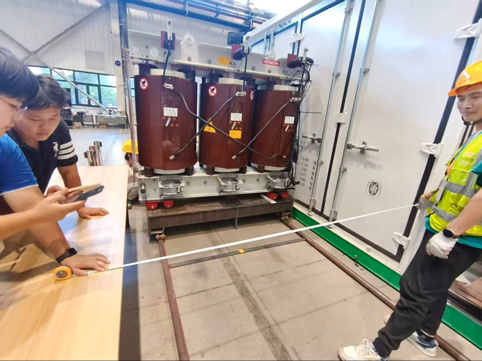
A complete three-phase cast-resin transformer — the vacuum-cast coils are the sealed heart of the unit, with no oil and no need for an external cooling tank.
Cooling: Managing the Heat
A transformer is not 100% efficient — and the small percentage it loses becomes heat. Two loss families matter:
Iron losses (no-load losses):
- hysteresis and eddy currents in the core, present whenever the transformer is energized.
Copper losses (load losses):
- resistive heating I²R in the windings, which grows with the square of the load current.
That heat must be carried away, or the winding temperature rises past what the insulation can survive — and insulation aging roughly doubles for every temperature step above its rating, silently shortening transformer life.
This is where the transformer's cooling designation matters. Dry-type transformers are rated by their cooling method:
AN (Air Natural):
- cooling relies on natural convection — warm air rises through the cooling ducts and fresh air is drawn in from below. Simple, silent, zero moving parts.
AF (Air Forced):
- fans force air through the cooling ducts, greatly increasing heat removal and allowing a much higher continuous output from the same core and windings.
We will come back to the AN/AF system in Part 3 — it is where the transformer meets our second product line.
Voltage Regulation: The Tap Changer
Supply voltage varies with grid conditions and distance from the source. To compensate, dry-type transformers are fitted with a tap changer — typically a de-energized tap switch offering a range such as ±2 × 2.5% around the nominal ratio. Your electrician selects the tap that matches your site's actual supply voltage, keeping the output within the required band. (Changing a de-energized tap requires the unit to be switched off and isolated first.)
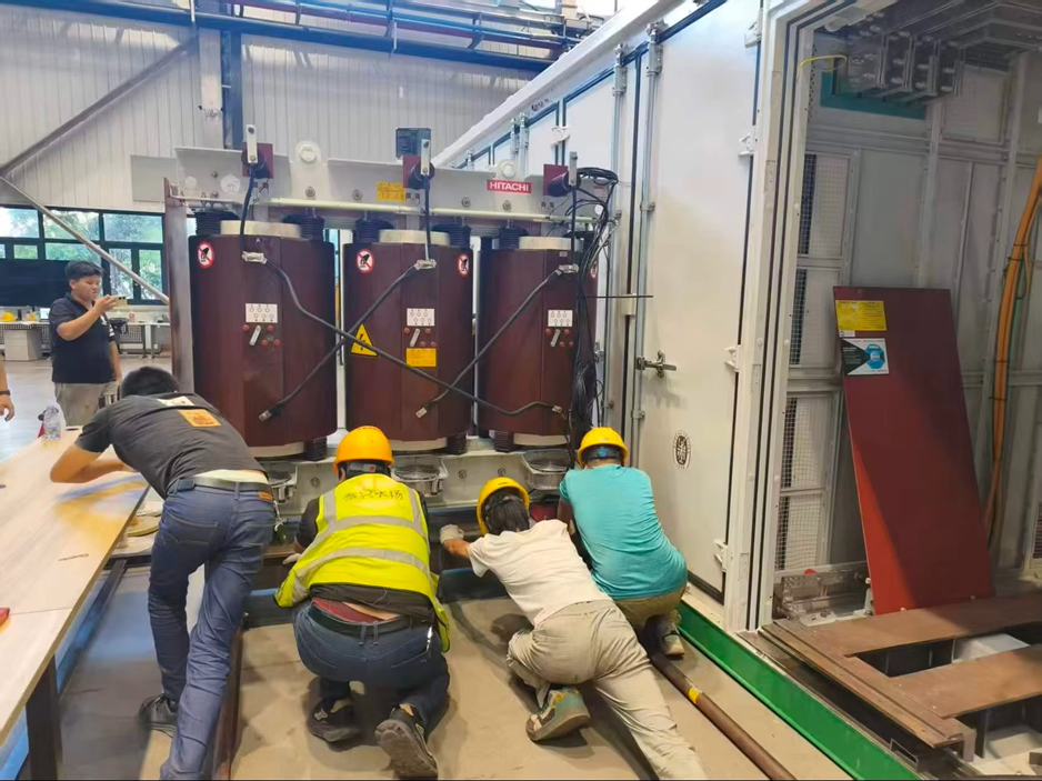
On-site installation and connection: tap selection, cable terminations, and busbar connections are completed before the unit is energized for service.
Part 2: How a Dry-Type Cooling Fan Works
The Principle: Moving Air, Moving Heat
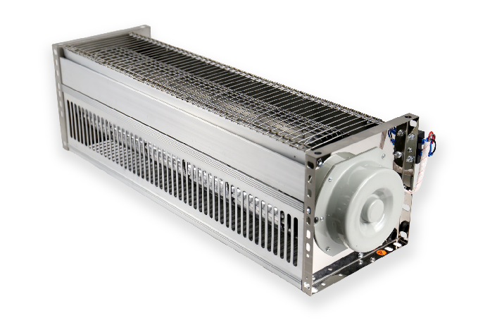
A dry-type cooling fan is an axial fan: a motor-driven impeller whose blades push air along the fan's axis, from intake to outlet. The physics is straightforward — spinning blades impart velocity to the air, creating a pressure difference that drives a continuous airflow.
What matters in a transformer application is not just airflow volume, but where that air goes. Fans are mounted so their output is directed into the transformer's cooling ducts — between and around the cast coils — so every cubic meter of air does useful cooling work instead of recirculating.
Blade Design and Aerodynamics
Fan blades are die-formed from high-strength aluminum alloy to an aerodynamic, airfoil-like profile. Blade geometry — diameter, chord, twist, and installation angle — determines the fan's operating point (airflow vs. static pressure). For transformer cooling, the design targets efficient airflow at the modest pressures needed to push air through narrow duct passages, while keeping noise acceptable for indoor installations.
Aluminum alloy is chosen for three reasons: it is light (lower bearing load), corrosion-resistant (long service in humid or industrial air), and easy to balance precisely.
The Motor: Reliable Rotation
Each fan is driven by an electric motor sized for continuous duty — transformer cooling fans may run for hours at a stretch on hot days. Motors are machine-wound for consistency, and the windings are impregnated with insulating varnish (or vacuum-pressure impregnated) to seal out moisture and improve heat transfer from the copper to the frame. Bearing selection targets low maintenance and long life in industrial environments, and motor insulation class is matched to the operating environment.
Dynamic Balancing: Smoothness Is Reliability
Every rotor assembly — blades, hub, and motor shaft — undergoes dynamic balancing before final assembly. Even a tiny mass imbalance produces vibration at running speed, which:
- shortens bearing life,
- generates noise,
- and — in the worst case — fatigues the mounting and surrounding structure.
Balancing to a tight residual tolerance is not a refinement; it is a reliability requirement for equipment expected to run unattended for years.
Sealed for the Real World
The fan enclosure is sealed to an IP55-style protection class, protecting the motor and bearings against dust and water jets — essential for outdoor transformer installations and dusty industrial rooms. Mounting frames are designed to bolt directly onto transformer cooling ducts or enclosure panels, which brings us to the system view.
Part 3: How They Work Together — The AN/AF System
The transformer and the fan are designed as one thermal system, and the operating logic is simple and automatic:
At normal load,
1. the transformer runs in AN mode— natural convection is enough, no fan, no noise, no moving parts to wear.
As load rises,
2. winding temperature climbs. A temperature controller (with sensors embedded in the windings) continuously monitors the temperature.
At the set threshold,
3. the controller starts the fans — the transformer switches to AF mode, forced airflow dramatically increases heat removal, and the transformer can deliver a substantially higher continuous output from the same core and windings.
When load drops
4. and temperature falls back below the threshold, the controller stops the fans and the unit returns to silent natural cooling.
This staged design is why a cast-resin transformer with fans can be physically smaller than an oil-filled unit of the same rating: the fan capacity is "borrowed" only when the load demands it. The same controller also provides over-temperature alarms and, in configured systems, can trip the load if the winding temperature ever reaches a critical level — protecting the asset from thermal abuse.
In-service operation: the transformer runs automatically under the AN/AF temperature logic, and routine inspection is performed from outside the sealed, energized enclosure — never by opening the door while it is live.
Part 4: Why Understanding the Principles Matters for Buyers
The operating principles above translate directly into practical decisions:
Specification:
- if your load profile includes sustained high demand or hot ambient conditions, specify the AF (fan-cooled) rating and ensure the fans are included in the enclosure design — don't discover the gap after installation.
Maintenance:
- a dry-type transformer itself has almost no wearing parts; the fans are the moving components. Periodic checks — blade condition, bearing noise, fan direction, airflow — are the only routine mechanical maintenance the system needs.
Service life:
- the single biggest controllable factor in transformer longevity is temperature. Keeping the cooling path clean and the fans working is how you protect a decades-long investment.
Diagnosis:
- when you understand the AN/AF logic, an unexpected fan start or persistent fan running is a useful signal — it tells you the transformer is being loaded harder than before, or that airflow is obstructed.
Conclusion
A dry-type transformer converts voltage through electromagnetic induction, guides its magnetic field through a grain-oriented steel core, and protects its windings with vacuum-cast epoxy resin. A dry-type cooling fan moves air on demand — designed, balanced, and sealed to keep that transformer within its thermal limits for decades. Together, they form an automatic thermal system: silent and passive at normal load, powerful and responsive when the load demands it.
Understanding the principles is the first step toward specifying, operating, and maintaining equipment that will still be performing reliably long after the purchase order is forgotten.
If you are planning a project and need a transformer and cooling system matched to your real load profile, send us your specifications — rated capacity, voltage, ambient conditions, and load pattern — and our engineers will help you select the right configuration.
Contact Shanghai Angeda — transformers and cooling fans, engineered as one system.
Suggested SEO Meta (for your website)
Meta title:
- How Dry-Type Transformers and Cooling Fans Work | Operating Principles — Shanghai Angeda
Meta description:
- How dry-type transformers and dry-type cooling fans work: electromagnetic induction, CRGO steel cores, vacuum-cast epoxy insulation, AN/AF cooling logic, and axial fan design — explained for buyers.
Target keywords:
- dry type transformer working principle, how does a dry type transformer work, cast resin transformer operating principle, dry type transformer cooling fan working, AN AF transformer cooling, axial fan for transformer cooling
Table of Contents
- How They Work: The Operating Principles of Dry-Type Transformers and Cooling Fans
- Introduction
- Part 1: How a Dry-Type Transformer Works
- Part 2: How a Dry-Type Cooling Fan Works
- Part 3: How They Work Together — The AN/AF System
- Part 4: Why Understanding the Principles Matters for Buyers
- Conclusion
- Suggested SEO Meta (for your website)