Transformatorët e tipit të thatë janë përbërës kryesorë në sistemet moderne të shpërndarjes së energjisë elektrike, veçanërisht në instalimet brenda ndërtesave dhe ato që janë të ndjeshme nga pikëpamja mjedisore, ku transformatorët me vaj janë të pa praktikueshëm ose të ndaluar. Këta transformatorë mbështeten në ftohjen me ajër të detyruar për të shpërndarë nxehtësinë e gjeneruar gjatë funksionimit, duke bërë zgjedhjen e ventilatorëve të përshtatshëm për ftohje një vendim kryesor në dizajn. Zgjedhja midis ventilatorëve centrifugal dhe ventilatorëve të rrjedhës kros (cross-flow) ndikon drejtpërdrejt në efikasitetin e transformatorit, në nivelet e zhurmës gjatë operimit, në kërkesat e mirëmbajtjes dhe në besueshmërinë e përgjithshme të sistemit. Kuptimi i ndryshimeve themelore midis këtyre dy teknologjive të ventilatorëve dhe i aplikimeve specifike të tyre në sistemet e ftohjes së transformatorëve lejon inxhinierëve dhe menaxherëve të objekteve të marrin vendime të informuara që optimizojnë edhe performancën edhe kostot totale të pronësisë.
Zgjedhja e ventilatorit të ftohjes për transformatorët me tipar të thatë duhet të marrë në konsiderim shumë parametra teknikë, përfshirë kërkesat për vëllimin e rrjedhës së ajrit, aftësitë për presion statik, kufizimet e hapësirës, kufizimet akustike dhe objektivat për konsumin e energjisë. Edhe pse edhe ventilatorët centrifugalë edhe ata me rrjedhë të kryqëzuar mund të ofrojnë zgjidhje efektive ftohëse, parimet e tyre operative të ndryshme dhe karakteristikat e performancës bëjnë që secila teknologji të jetë më e përshtatshme për konfigurime specifike transformatorësh dhe mjedise instalimi. Ky udhëzues i hollësishëm analizon ndryshimet mekanike midis këtyre llojeve të ventilatorëve, vlerëson avantazhet dhe kufizimet e tyre respektive në zbatimet e ftohjes së transformatorëve dhe ofron kriteret praktike të zgjedhjes për t’ju ndihmuar të përzgjidhni zgjidhjen optimale të ftohjes për instalimin tuaj specifik të transformatorit me tipar të thatë.
Parimet Operative Themelore dhe Dallimet Mekanike
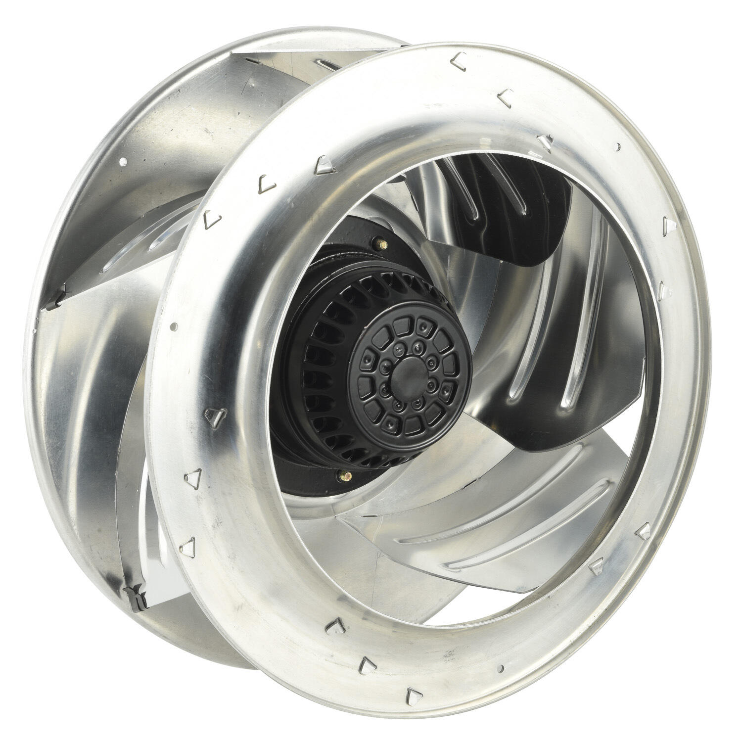
Dizajni i Ventilatorit Centrifugal dhe Mekanika e Rrjedhës së Ajrit
Një ventilator centrifugal funksionon duke tërhequr ajrin në impeler përgjatë boshtit të tij rrotullues dhe më pas e shpërndan atë radialisht jashtë përmes forcës centrifugale. Impeleri përbëhet nga shumë blada të lakuar të montuara midis dy pllakave rrethore, duke krijuar një shtëpi me formë spirale që konverton efikasishëm energjinë kinetike rrotulluese në shtypje statike. Kur përdoret për ftohjen e transformatorëve të tipit pa vaj, helm centrifug ventilatori zakonisht montohet në mbulesën e transformatorit me tuba që drejtojnë rrjedhën e përqendruar të ajrit përmes bobinave dhe bërthamës së transformatorit. Kjo dizajnimi shkëlqen në prodhimin e shtypjes statike të lartë, duke i lejuar ventilatorit të kapërcejë rezistencën e krijuar nga konfigurimet e dendura të bobinave, kanalët e ngushta të ftohjes dhe tubat e gjatë që shpesh hasen në instalimet e transformatorëve më të mëdhenj.
Gjeometria e pllakave të ventilatorit centrifugal ndikon në mënyrë të konsiderueshme në karakteristikat e performancës së tij në zbatime të transformatorëve. Pllakat me lakim të përparshëm prodhojnë vëllime më të larta ajri në shpejtësi më të ulëta dhe në nivele zëri më të ulëta, gjë që i bën ato të përshtatshme për transformatorët në ambiente të ndjeshme ndaj zërit, si p.sh. spitalët ose ndërtesat zyri. Pllakat me lakim të prapshëm dhe pllakat me formë aerofoli ofrojnë efikasitet më të lartë dhe mund të përballojnë temperatura më të larta pa degradim të performancës, çka është e avantazhshme për transformatorët që punojnë nën ngarkesa të vazhdueshme të rënda. Ndërtimi i fortë i impelereve të ventilatorëve centrifugal lejon që ata të ruajnë performancën e tyre të qëndrueshme edhe kur ekspozohen ndaj temperaturave të ngritura dhe fushave elektromagnetike që gjenden në ambientet e transformatorëve, duke kontribuar në jetëgjatësinë më të gjatë të shfrytëzimit dhe në intervalë më të shkurtër mirëmbajtjeje.
Konfigurimi i Ventilatorit Me Rrymë Kryqore dhe Modeli i Shpërndarjes së Ajrit
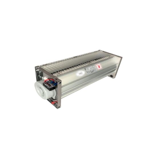
Ventilatorët me rrjedhë kryq, të njohur edhe si ventilatorë tangencialë ose ventilatorë tubularë, përdorin një impelër cilindrik me blada të lakuar përpara që shtrihen në gjithë gjatësinë e zonës së ftohjes. Ajri hyr në impelër tangjencialisht nga njëra anë, kalon nëpër vargun e bladave ku fiton shpejtësi dhe del tangjencialisht nga ana tjetër, duke krijuar një perde uniforme ajri në gjithë gjatësinë e montimit të ventilatorit. Kjo model i veçantë i rrjedhës së ajrit bën që ventilatorët me rrjedhë kryq të jenë veçanërisht të përshtatshëm për aplikime që kërkojnë shpërndarje të barabartë ajri mbi sipërfaqe të gjerë, siç janë kanalët vertikale të ftohjes në disa dizajne transformatorësh të llojit pa vaj. Hapja e daljes drejtkëndore e zgjatur prodhon një profil të rrjedhës së ajrit të sheshtë dhe të gjerë që mund të mbulojë gjithë gjerësinë e bobinave të transformatorit pa kërkuar rregullime komplekse tubash.
Thjeshtësia mekanike e ndërtimit të ventilatorëve me rrjedhë kryqore ofron avantazhe specifike në aplikimet e ftohjes së transformatorëve, ku efikasiteti i hapësirës dhe qasja lehtë për mirëmbajtje janë prioritet. Këta ventilatorë kanë më pak pjesë lëvizëse se sistemet e ventilatorëve centrifugal të ngjashëm, dhe dizajni modular i tyre lejon zëvendësimin e thjeshtë pa çmontuar seksione të mëdha të mbulesës së transformatorit. Hapësira e vogël e instalimit të ventilatorëve me rrjedhë kryqore e mundëson integrimin e tyre në dizajne të kompaktë të transformatorëve, ku kufizimet e hapësirës vertikale ose horizontale do të parandalonin përdorimin e konfigurimeve tradicionale të ventilatorëve centrifugal. Megjithatë, ventilatorët me rrjedhë kryqore prodhojnë në përgjithësi presion statik më të ulët se ventilatorët centrifugal me konsumim të njëjtë energjie, gjë që kufizon efikasitetin e tyre në aplikimet që kërkojnë rrjedhë ajri nëpër pasaje të kufizuara ose kundër presionit të kthyer të lartë.
Karakteristikat e Performancës Krahasuese në Transformer Mjedise
Kur vlerësohen teknologjitë e ventilatorëve për ftohjen e transformatorëve me tip të thatë, marrëdhënia midis volumit të rrjedhës së ajrit, aftësisë së presionit statik dhe efikasitetit energjetik bëhet e thelbësishme. Projektimet e ventilatorëve centrifugale zakonisht arrijnë raporte më të larta të presionit, të matura si raport i presionit të daljes ndaj presionit të hyrjes, gjë që përkthehet në performancë më të mirë kur forcohen ajri përmes gjeometrive të komplikuara të brendshme të bobinave të transformatorit, veçanërisht në njësitë me kapacitet më të lartë. Kjo aftësi e gjenerimit të presionit lejon ventilatorët centrifugalë të ruajnë një rrjedhë ajri adekuate edhe kur bobinat e transformatorit grumbullojnë pluhur ose kur zhvillohen pengesa të vogla në pasazhet e ftohjes gjatë periudhave të gjata të operimit. Mundësia për të specifikuar ventilatorë centrifugalë me diametra të ndryshme impellesh dhe shpejtësi rrotullimi ofron fleksibilitet në projektim për të përshtatur kërkesat e specifika të shpërndarjes së nxehtësisë së transformatorit në një gamë të gjerë rating-esh të fuqisë.
Ventilatorët me rrjedhë të kryqëzuar tregojnë avantazhe në aplikimet ku shpërndarja uniforme e temperaturës në sipërfaqet e transformatorëve është më e rëndësishme se kapaciteti maksimal i ftohjes. Kullimi i vazhdueshëm i ajrit që prodhojnë ventilatorët me rrjedhë të kryqëzuar minimizon pikat e nxehta që mund të formohen kur ftohja nga një burim i vetëm (ventilatorët centrifugalë) krijon gradientë të papajisur të temperaturës në sipërfaqet e bobinave. Kjo karakteristikë e ftohjes uniforme mund të zgjasë jetëgjatësinë e izolimit të transformatorit duke parandaluar përqendrimet lokale të stresit termik. Për më tepër, shpejtësitë më të ulëta rrotulluese që përdoren zakonisht nga ventilatorët me rrjedhë të kryqëzuar për të arritur vëllime të barabarta të rrjedhës së ajrit rezultojnë në zvogëlim të emisioneve akustike, gjë që është e vlefshme në instalimet e transformatorëve brenda ndërtesave të banuara ose në mjedise urbane me rregulla të ashpra zanore. Kompromisi përfshin pranimin e një kapaciteti maksimal më të ulët të shpërbëritjes së nxehtësisë dhe të një aftësie më të ulët për të kapërcyer pengesat e rrjedhës së ajrit në krahasim me alternativat e ventilatorëve centrifugalë.
Përparësitë specifike të aplikimit për ftohjen e transformatorëve të tipit të thatë
Përparësitë e ventilatorëve centrifugal në sistemet me kapacitet të lartë dhe me shumë tuba
Transformatorët e madhësisë së thatë me fuqi mbi 1000 kVA përdorin zakonisht sisteme ftohje me ventilatorë centrifugal, pasi këta kanë aftësi të jashtëzakonshme për të lëvizur vëllime të mëdha ajri përmes rrjetave komplekse tubash. Këta transformatorë me kapacitet më të lartë kanë shpesh shumë kanale të brendshme ftohje me kthesa këndi të drejtë, kalime midis seksioneve të ndryshme të tubave dhe shtigje ajri të gjata që krijojnë rezistencë të konsiderueshme ndaj rrjedhës së ajrit. Aftësia e lartë e ventilatorëve centrifugal për të gjeneruar presion statik siguron shpejtësi të mjaftueshme ajri në të gjitha këto kalime të kufizuara, duke mbajtur transferimin efikas të nxehtësisë nga sipërfaqet e bërthamës dhe të bobinave edhe në seksionet më të thella të montimit të transformatorit. Kjo aftësi për të krijuar presion bëhet gjithnjë e më e rëndësishme kur madhësia e transformatorit rritet dhe shtigjet e brendshme të rrjedhës së ajrit bëhen më të gjata dhe më të komplikuara.
Ambientet industriale me pluhur ambiental, fibra ose kontaminim me grimca përfitojnë veçanërisht nga instalimet e ventilatorëve centrifugal të pajisur me sisteme filtrimi të përshtatshme. Konfigurimi i përqendruar i hyrjes së ventilatorëve centrifugal lehtëson integrimin e filtreve me efikasitet të lartë që mbrojnë bobinat e transformatorit nga kontaminimi, ndërkohë që kapaciteti i shtypjes së ventilatorit tejkalon rezistencën shtesë që sjellin mesat e filtrimit. Fabrikat e prodhimit, operacionet tekstil dhe fabrikat e përpunimit bujqësor janë ambientet tipike ku kjo aftësi filtrimi tregon se është e domosdoshme për ruajtjen e besueshmërisë së transformatorit. Aftësia e sistemeve të ventilatorëve centrifugal për të tërhequr ajër të filtruar nga vendndodhje të largëta përmes tubave të gjata të ajrit lejon edhe vendosjen e transformatorit në pozicionet optimale të shpërndarjes elektrike, pavarësisht nga kushtet e cilësisë së ajrit lokal, duke ofruar fleksibilitet të vlefshëm të instalimit në hapësirat industriale të kufizuara.
Përparësitë e Ventilatorëve me Rrymë Kryq në Instalimet e Kompaktave dhe të Sensitiva ndaj Zhurmës
Transformatorët e vegjël të tipit pa vaj, që shërbejnë ndërtesa komerciale, qendra të dhënash dhe komplekse rezidenciale, përdorin shpesh ftohjen me ventilator kryq për të plotësuar kërkesat e ashpra akustike, duke ruajtur një hapësirë instalimi të vogël. Nivel i ulët natyror i zhurmës së ventilatorëve kryq rrjedh nga shpejtësitë e ulëta rrotulluese dhe mungesa e rrjedhës së turbulente të daljes, e cila është karakteristike për daljet e ventilatorëve centrifugal. Kur transformatorët instalohen në dhoma mekanike ngjitur me hapësira të okupuara, dhoma konferencash ose zona për gjumë, avantazhi akustik i ventilatorëve kryq shpesh tejkalon kapacitetin e tyre të ulët të shtypjes. Nivelet e zhurmës më të ulëta se 65 dBA në distancë një metër mund të arrihen pa përdorur mbulesa akustike ose trajtime të zgjatura të zbutjes së zhurmës, të cilat do të rrisnin kostot e instalimit dhe kompleksitetin e mirëmbajtjes.
Forma drejtkëndore dhe modeli i shpërndarjes së ajrit të ventilatorëve me rrjedhë kryq lejojnë dizajne inovative të mbulesave të transformatorëve që minimizojnë dimensionet e përgjithshme të pajisjeve. Transformatorët që shërbejnë dhomat e makinave të liftit, armatirat e telekomunikacionit dhe aplikimet e tjera me kufizime hapësire profitin nga aftësia për të integruar ventilatorët me rrjedhë kryq përgjatë gjithë gjerësisë së paneleve të ftohjes pa kërkuar thellësinë shtesë që nevojitet për të akomoduar mbulesat e ventilatorëve centrifugal dhe përkthimet e daljes. Kjo efikasitet gjeometrik lejon prodhuesve të transformatorëve të optimizojnë rregullimet e bërthamës dhe të spiralet për performancën elektrike pa komprometuar efikasitetin e ftohjes. Vëllimi i reduktuar i instalimit përkthehet drejtpërdrejt në kostot më të ulëta transporti, manipulim më të thjeshtë gjatë instalimit dhe mundësi të zgjeruara vendosjeje në ndërtesa ku hapësira mekanike ka vlerë të lartë.
Konsiderata për Efikasitetin Energetik dhe Kostot e Përdorimit
Konsumimi i energjisë nga ventilatorët e ftohjes përfaqëson një shpenzim operativ të vazhdueshëm gjatë tërë jetës së përdorimit të transformatorit, duke bërë efikasitetin e ventilatorëve një kriter kryesor të zgjedhjes për analizën e kostos së ciklit të jetës. Projektimet moderne të ventilatorëve centrifugal që përfshijnë motorë me komutim elektronik dhe gjeometri të optimizuara të impelereve arrijnë efikasitete mbi 70 përqind kur funksionojnë brenda intervalit të tyre të projektuar, duke shndërruar pjesën më të madhe të energjisë elektrike hyrëse në punë të dobishme të rrjedhës së ajrit. Këto fitime në efikasitet janë veçanërisht të rëndësishme në transformatorët që funksionojnë vazhdimisht, ku ventilatorët e ftohjes mund të punojnë 8760 orë në vit. Pajisjet me frekuencë të ndryshueshme, të kombinuara me ventilatorë centrifugal, lejojnë strategji ftohjeje të përshtatshme me ngarkesën, ku shpejtësia e ventilatorit modulohet sipas temperaturës së transformatorit, duke zvogëluar konsumin e energjisë gjatë periudhave të ngarkesës elektrike të vogël, ndërkohë që mbahet kapaciteti i duhur i ftohjes për intervalet e kërkesës maksimale.
Sistemet e ventilatorëve me rrjedhë kryq, edhe pse zakonisht tregojnë efikasitet maksimal më të ulët se dizajnet e optimizuara të ventilatorëve centrifugal, mund të ofrojnë ekonomi operimi të favorshme në aplikime me kërkesa modeste për ftohje dhe objektiva akustikë të favorshëm. Kërkesa e reduktuar elektrike e ventilatorëve më të vegjël me rrjedhë kryq, në krahasim me instalimet e ventilatorëve centrifugal të barabarta që prodhojnë nivele të ngjashme zhurme, mund të kompensojë efikasitetin aerodinamik më të ulët të tyre. Sistemet e kontrollit të aktivizuara nga temperatura, që ndalojnë dhe nisnin ventilatorët me rrjedhë kryq bazuar në sensorët e temperaturës së bobinave, në vend që të funksionojnë vazhdimisht, mund të zvogëlojnë edhe më shumë konsumin vjetor të energjisë në transformatorët që përjetojnë modele të ngarkesës së ndryshueshme. Analiza e plotë e kostos së ciklit të jetës duhet të marrë në konsiderim kostot fillestare të pajisjeve, shpenzimet e instalimit, orët vjetore të pritshme të punës, tarifat lokale të energjisë elektrike dhe kërkesat për mirëmbajtje, që të përcaktohet teknologjia e ventilatorëve ekonomikisht optimale për aplikime specifike të transformatorëve.
Kriteret e Zgjedhjes Bazuar në Specifikimet e Transformatorit dhe Kontekstin e Instalimit
Përputhja e Kapacitetit të Ventilatorit me Kërkesat e Ngarkesës Termike
Zgjedhja e përshtatshme e ventilatorit fillon me përcaktimin e saktë të kërkesave për shpërndarjen e nxehtësisë së transformatorit në kushtet e ngarkesës maksimale. Prodhuesit e transformatorëve të llojit të thatë zakonisht specifikojnë rrjedhën e ajrit të nevojshme për ftohje në kubik feet në minutë ose në metra kubikë në orë, bazuar në kapacitetin e deklaruar të transformatorit, karakteristikat e impedancës dhe rritjen e lejuar të temperaturës. Për transformatorët standard me rritje të temperaturës prej 80 ose 115 gradë Celsius, sistemi i ftohjes duhet të heqë midis 2,5 dhe 4,0 përqind të kapacitetit të deklaruar të transformatorit si nxehtësi e humbur, varësisht nga efikasiteti i dizajnit të bërthamës dhe konfigurimi i bobinave. Ventilatorët centrifugalë, me aftësitë e tyre të superiorë në krijimin e shtypjes, janë përgjithësisht të nevojshëm për transformatorët ku rezistenca e brendshme e rrjedhës së ajrit tejkalon 0,5 inç kolonë uji, gjë që korrespondon përafërsisht me njësitë me kapacitet mbi 750 kVA me dizajne konvencionale të pasajeve të ftohjes.
Ventilatorët me rrjedhë të kryqëzuar bëhen alternativa të përshtatshme për transformatorët me arkitektura më të hapura të ftohjes, ku kërkesat për shtypje statike mbeten nën 0,3 inç kolonë uji. Këto dizajne me rezistencë më të ulët përfshijnë zakonisht kanale ftohëse më të gjera, shtigje më të shkurtra për rrjedhën e ajrit dhe ndryshime më pak drejtimi, të cilat do të kërkonin aftësitë e shtypjes të ventilatorëve centrifugalë. Projektuesit e transformatorëve mund të optimizojnë gjeometrinë e bobinave dhe konfigurimin e bërthamës për të përshtatur karakteristikat e ventilatorëve me rrjedhë të kryqëzuar kur zvogëlimi i zhurmës ose efikasiteti i hapësirës është prioritet mbi maksimizimin e kapacitetit elektrik në një vëllim të caktuar të kabinës. Modelimi termik duhet të marrë parasysh faktorët e korrigjimit për lartësinë, temperaturat maksimale të pritura ambientale dhe çdo reduktim të kapacitetit që kërkohet për instalimin në hapësira të ngushta ose kabinë me hapje të kufizuara të ventilimit, të cilat rrisin shtypjen e kundërt efektive kundrejt së cilës duhet të punojnë ventilatorët.
Kufizimet Ambientale dhe Rregullative
Karakteristikat e mjedisit të instalimit shpesh përcaktojnë zgjedhjen e teknologjisë së ventilatorëve, pavarësisht nga konsideratat e vetme të performancës termike. Instalimet e transformatorëve jashtë ndërtesave, të ekspozuara ndaj shiut, kripës në ajër në zonat bregdetare ose ndryshimeve ekstreme të temperaturës, kërkojnë montime ventilatorësh me vlera të përshtatshme të mbrojtjes mjedisore dhe materiale rezistente ndaj korrozionit. Ventilatorët centrifugalë të dizajnuar për mjedise të rënda kanë mbulesa të mbyllura të motorëve, impelere prej qeliku inox ose alumini me mbulim dhe konfigurime të hyrjeve të mbrojtura nga moti, të cilat parandalojnë hyrjen e ujit duke ruajtur në të njëjtën kohë efikasitetin e ftohjes. Këto ndërtime të forta të ventilatorëve centrifugalë zakonisht i rezistojnë kushteve jashtë ndërtesave më besnikrisht se ventilatorët me rrjedhë të kryqëzuar, të cilët janë projektuar kryesisht për instalime brenda ndërtesave ose në vendet e mbrojtura, ku impelerët cilindrikë të tyre të ekspozuar nuk do të hasin ekspozim direkth në kushtet e motit.
Rregullimet akustike në zonat urbane ose institucionale mund të vendosin kufizime shumë të ashpra për nivelin e zërit, që eliminon zgjidhjet konvencionale me ventilatorë centrifugalë nga konsiderimi, edhe pse këto kanë avantazhe në performancë. Kodet e ndërtimit në zonat rezidenciale shpesh kufizojnë zhurmën e pajisjeve mekanike në 55 dBA ose më pak gjatë orëve të natës, një nivel që arrihet vetëm me përdorimin e ventilatorëve me rrjedhë të kryqëzuar ose me sisteme të ventilatorëve centrifugalë me zbutje të thellë akustike dhe mbulesa akustike që rrisin kushtet në mënyrë të konsiderueshme. Fasilitetet shëndetësore, institucionet arsimore dhe zhvillimet rezidenciale luksuese specifikojnë zakonisht kriteret maksimale të zërit që favorizojnë zgjedhjen e ventilatorëve me rrjedhë të kryqëzuar, edhe kur rezultojnë kosto fillestare më të larta ose mbulesa më të mëdha të transformatorëve. Kërkesat për izolimin e vibracioneve ndikojnë po ashtu në zgjedhjen e teknologjisë së ventilatorit, pasi ekuilibri i natyrshëm i impelereve cilindrike të ventilatorëve me rrjedhë të kryqëzuar prodhon më pak transmetim vibracionesh strukturore se sa aranzhimi i ngarkuar në pikë i palosjeve të impelereve të ventilatorëve centrifugalë.
Qasja për Mirëmbajtje dhe Shitjet e Pritura të Jetës së Shërbimit
Kërkesat e mirëmbajtjes në afat të gjatë dhe strategjitë për zëvendësimin e komponentëve duhet të udhëheqin zgjedhjen e teknologjisë së ventilatorëve për aplikimet e ftohjes së transformatorëve. Montazhet e ventilatorëve centrifugal përdorin zakonisht konfigurime standarde të motorëve dhe rrotulluesve që lehtësojnë zëvendësimin në terren duke përdorur komponentë që janë në dispozicion të përgjithshëm, duke reduktuar kërkesat për stokim dhe minimizuar kohën e ndalimit gjatë intervenimeve të mirëmbajtjes. Rregullimi i veçuar i motorit dhe impelerit në shumicën e dizajneve të ventilatorëve centrifugal lejon zëvendësimin e rrotulluesve pa disturbuar montazhin e impelerit të balancuar me kujdes, duke zgjatur intervalin midis riparimeve të mëdha. Ventilatorët centrifugal të klasës industriale, të dimensionuar në mënyrë të përshtatshme për aplikimet e ftohjes së transformatorëve, arrijnë zakonisht 100.000 orë funksionimi para se të kërkojnë zëvendësimin e rrotulluesve, çka korrespondon me rreth 11 vjet operimi të vazhdueshëm ose një jetë shërbimi shumë më të gjatë në transformatorët me kontroll të ventilatorit të përshtatur sipas temperaturës.
Procedurat e mirëmbajtjes së ventilatorëve me rrjedhë kryq ndryshojnë në varësi të faktit se a përdoren motorë me rotor të jashtëm me impelera të integruara apo motorë konvencionalë me montime të veçanta të impelerave. Projektimet e integruara ofrojnë instalim fillestar më të thjeshtë dhe dimenzione më të vogla, por mund të kërkojnë zëvendësimin e plotë të ventilatorit kur ndodhin dëmtimi i motorit ose i palosjeve, duke rritur kështu kostot e ciklit të jetës, edhe pse çmimet fillestare të pajisjeve janë më të ulëta. Gjatësia e zgjatur dhe shpejtësitë më të ulëta rrotulluese të ventilatorëve me rrjedhë kryq rezultojnë zakonisht në ngarkesa më të vogla për palosjet krahasuar me ventilatorët centrifugalë me kapacitet të njëjtë, gjë që mund të zgjasë intervalet e mirëmbajtjes. Megjithatë, ekspozimi i vazhdueshëm i bladave të impelerit të ventilatorit me rrjedhë kryq ndaj rrjedhës së ajrit i bën ato më të prekshme nga akumulimi i pluhurit dhe degradimi i performancës në instalimet ku nuk ka filtrim adekuat, gjë që kërkon pastrime periodike për të ruajtur shkallën e projektuar të rrjedhës së ajrit dhe për të parandaluar konditat e nxehtësisë së tepërt në transformator.
Strategjitë e Zbatimit Praktik dhe Integrimi i Sistemit
Qasjet Hibride për Ftohje për Performancë Optimale
Disa dizajne të avancuara të transformatorëve të tipit të thatë përdorin strategji hibride ftohjeje që kombinojnë teknologjitë e ventilatorëve centrifugal dhe me rrjedhë të kryqëzuar, për të shfrytëzuar avantazhet e veçanta të secilës qasje. Transformatorët e fuqisë së lartë mund të përfshijnë ventilatorë centrifugal për ftohjen primare të bërthamës, ku presioni statik i lartë është i nevojshëm për të detyruar ajrin nëpër laminimet e ngushta, ndërkohë që njëkohësisht përdorin ventilatorë me rrjedhë të kryqëzuar për ftohjen e bobinave, ku prioritet kryesor është shpërndarja uniforme e ajrit në sipërfaqet e bobinave. Ky qasje e kombinuar optimizon performancën termike, duke menaxhuar njëkohësisht emisionet akustike dhe kufizimet e hapësirës së instalimit. Sistemet e kontrollit për konfigurimet hibride zakonisht rendisin operimin e ventilatorëve në bazë të ngarkesës së transformatorit, duke aktivizuar ventilatorët më të qetë me rrjedhë të kryqëzuar gjatë periudhave të ngarkesës së lehtë dhe duke aktivizuar ventilatorët centrifugal me kapacitet më të lartë vetëm kur kushtet termike kërkojnë kapacitet maksimal ftohjeje.
Aplikimet e rikonstruksionit ku transformatorët ekzistues të tipit të thatë kërkojnë përmirësime të sistemit të ftohjes paraqesin mundësi për të rivlerësuar përzgjedhjen origjinale të teknologjisë së ventilatorit bazuar në përvojën operative dhe rrethanat e ndryshuara. Transformatorët e pajisur fillimisht me ventilatorë centrifugale që gjenerojnë nivele të papranueshme zhurme në përdorimet e modifikuara të ndërtesave mund të pranojnë zëvendësime të ventilatorëve me rrjedhë tërthore nëse modelet e ngarkesës elektrike janë zvogëluar ose nëse modifikimet në kalimet e brendshme të ftohjes mund të zvogëlojnë rezistencën e rrjedhës së ajrit. Anasjelltas, transformatorët që përjetojnë probleme termike me instalimet origjinale të ventilatorëve me rrjedhë tërthore mund të përfitojnë nga rikonstruksionet e ventilatorëve centrifugale që ofrojnë aftësi të shtuar presioni për të kapërcyer ndotjen e akumuluar ose për të kompensuar efikasitetin e reduktuar të ftohjes ndërsa materialet izoluese plaken. Planifikimi i duhur i rikonstruksionit kërkon modelim termik të konfigurimit ekzistues të transformatorit dhe vlerësim të kujdesshëm të kufizimeve fizike që mund të kufizojnë opsionet e montimit të ventilatorit ose të kërkojnë modifikime në hapjet e ventilimit të mbylljes.
Integrimi i Sistemit të Kontrollit dhe Menaxhimi i Temperaturës
Sistemet moderne të ftohjes së transformatorëve integrojnë funksionimin e ventilatorëve me sistemet e monitorimit dhe kontrollit të temperaturës, të cilat optimizojnë performancën duke minimizuar konsumin e energjisë dhe zgjatuar kohën e përdorimit të komponentëve. Detektorët e rezistencës së temperaturës të vendosur brenda bobinave të transformatorit ofrojnë përgjithmonë informacion termik në kontrolerët programues, të cilët rregullojnë funksionimin e ventilatorëve sipas nevojave aktuale të shpërndarjes së nxehtësisë, në vend që të punojnë vazhdimisht me shpejtësi të fiksuara. Instalimet e ventilatorëve centrifugal përdorin zakonisht drejtimet me frekuencë të ndryshueshme (VFD) që rregullojnë shpejtësinë e motorit proporcionalisht me kërkesën për ftohje, duke zvogëluar konsumin elektrik gjatë periudhave me ngarkesë të ulët, por duke ruajtur kapacitetin për intervalet e kërkesës maksimale. Efikasiteti i lartë i ventilatorëve centrifugal në kushtet e ngarkesës pjesore i bën ato veçanërisht të përshtatshme për strategjitë e kontrollit me shpejtësi të ndryshueshme, të cilat mund të zvogëlojnë kostot vjetore të energjisë me 30 deri në 50 përqind në krahasim me operimin me shpejtësi konstante.
Sistemet e kontrollit të ventilatorëve me rrjedhë kryq përdorin shpesh operimin e ndarë në etapa 'për-pa', ku disa njësi më të vogla ventilatorësh aktivizohen në mënyrë të njëpasnjëshme kur temperatura e transformatorit rritet, duke ofruar kapacitet të ndarë të ftohjes që i afrohet modulimit të vazhdueshëm të mundshëm me motorë ventilatorësh centrifugal me shpejtësi të ndryshueshme. Ky qasje e ndarë në etapa është më e përshtatshme për karakteristikat e ventilatorëve me rrjedhë kryq se sa kontrolli me shpejtësi të ndryshueshme, pasi këta ventilatorë tregojnë degradim më të thellë të performancës në shpejtësi të ulët krahasuar me dizajnet centrifugal. Pika të vendosura të temperaturës për aktivizimin e ventilatorëve duhet të ruajnë temperaturën e spiraletave të paktën 10 gradë Celsius më të ulët se vlerat maksimale të regjistruara, për të kompensuar pikat lokale të nxehta, variacionet e vendosjes së sensorëve dhe tranzientet e ngarkesës të përkohshme që mund të ndodhin midis intervaleve të mostrimit të sistemit të kontrollit. Funksionet e alarmeve që informojnë operatorët e objektit për dështimet e ventilatorëve ose trendet anormale të temperaturës lejojnë intervenime parandaluese mirëmbajtjeje që pengojnë dëmtimin e transformatorit dhe shmangin çregullimet e paplanifikuara që kushtojnë shumë.
Praktikat Më të Mirë të Instalimit dhe Verifikimi i Punësimit
Praktikat e duhura të instalimit ndikojnë në mënyrë të konsiderueshme në performancën reale të sistemeve të ftohjes me ventilator centrifugal dhe me rrjedhë të kryqëzuar në aplikimet me transformatorë me tipar të thatë. Montimi i ventilatorit centrifugal kërkon një mbështetje strukturore të fortë që parandalon transmetimin e vibracioneve te strukturat e ndërtesave, duke ruajtur në të njëjtën kohë aligjimin e saktë midis montimeve të motorit dhe impelerit për të minimizuar konsumimin e rrotulluesve dhe gjenerimin e zhurmës. Lidhjet e fleksibla me tuba midis daljes së ventilatorit centrifugal dhe hapjeve të hyrjes së transformatorit lejojnë zgjerimin termik dhe parandalojnë përqendrimin e stresit që mund të shkaktojë lodhje të pikave të lidhjes gjatë cikleve termike. Ekranet ose filtrat e hyrjes duhet të ofrojnë sipërfaqe të lirë të mjaftueshme për të parandaluar rënien e tepërt të presionit, e cila do të zvogëlojë kapacitetin e ventilatorit dhe do të rrisë konsumin e energjisë, duke ruajtur në të njëjtën kohë integritetin strukturor të mjaftueshëm për të parandaluar çrrëzimin e tyre nën kushtet e presionit negativ.
Instalimet e ventilatorëve me rrjedhë të kryqëzuar kërkojnë vëmendje të veçantë për hermetizimin e ndërfaqeve midis korpuseve të ventilatorëve dhe mbulesave të transformatorëve, që të parandalohet shkurtimi i ajrit të ftohjes, i cili do të zvogëlojë efikasitetin termik. Mënyra e shpërndarjes së rrjedhës së ajrit nga ventilatorët me rrjedhë të kryqëzuar varet nga ruajtja e diferencave të presionit në gjithë gjatësinë e plenumit të daljes, prandaj kërkohet vëmendje e kujdesshme për kapakët e skajshëm dhe flanxhet e montimit, të cilat mund të leshojnë ajër nëse nuk janë hermetizuar si duhet. Procedurat e punësimit (commissioning) për të gjitha sistemet e ftohjes së transformatorëve duhet të përfshijnë verifikimin e rrjedhës së aktualë të ajrit në krahasim me specifikimet projektuese duke përdorur instrumente të kalibruara, konfirmimin e rritjes së temperaturës nën kushtet e ngarkesës dhe dokumentimin e performancës akustike në vendndodhjet e specifikuara të matjeve. Këto matje verifikuese vendosin të dhënat bazë të performancës, të cilat mbështesin programet e vazhdueshme të monitorimit të gjendjes dhe ofrojnë kriteret objektive për vlerësimin e kërkesave të ardhshme të mirëmbajtjes ose të modifikimeve të sistemit.
Pyetje të shpeshta
Cili është ndryshimi kryesor midis ventilatorëve centrifugal dhe ventilatorëve me rrjedhë të kryqëzuar në ftohjen e transformatorëve?
Ndryshimi themelor qëndron në mekanizmat e tyre të gjenerimit të rrjedhës së ajrit dhe në karakteristikat e performancës që rezultojnë. Ventilatorët centrifugal tërheqin ajrin në mënyrë aksiale dhe e shpërqëndrojnë atë në mënyrë rrezore duke përdorur forcën centrifugale, duke krijuar presion statik të lartë, i cili është i përshtatshëm për të shtyrë ajrin nëpër kalime të kufizuara në transformatorët më të mëdhenj. Ventilatorët me rrjedhë të kryqëzuar lëvizin ajrin tangjencialisht nëpër një impelerr cilindrik, duke prodhuar një tendë uniforme rrjedhe ajri, ideale për shpërndarjen e barabartë të temperaturës në sipërfaqe të gjerë, por me aftësi të ulët të gjenerimit të presionit. Ventilatorët centrifugal dallohen në aplikimet që kërkojnë kapacitet të lartë ftohjeje dhe aftësinë për të kapërcyer rezistencën e konsiderueshme të rrjedhës së ajrit, ndërsa ventilatorët me rrjedhë të kryqëzuar ofrojnë avantazhe në ambiente ku zëri është i ndjeshëm dhe në instalime me hapësirë të kufizuar, ku shpërndarja e barabartë e ftohjes është më e rëndësishme se gjenerimi maksimal i presionit.
Si mund të përcaktoj se cili lloj ventilatori është i përshtatshëm për transformatorin tim me izolim të thatë?
Zgjedhja e ventilatorit varet nga shumë faktorë, përfshirë kapacitetin e transformatorit, rezistencën e kalimeve të brendshme të ftohjes, ambientin e instalimit, kërkesat akustike dhe kufizimet e hapësirës. Transformatorët me rating mbi 750 kVA ose ata me kanale të ndërlikuara të brendshme zakonisht kërkojnë ventilatorë centrifugalë për të gjeneruar shtypje statike të mjaftueshme për rrjedhën e ajrit të mjaftueshme. Njësitë më të vogla në vendet ku kërkohet ulja e zërit, si spitale apo ndërtesa zyri, shpesh profitojnë nga ventilatorët me rrjedhë të kryqëzuar që funksionojnë më ngadale. Llogarisni kërkesat e transformatorit për shpërndarjen e nxehtësisë, matni hapësirën e disponueshme për instalim, identifikoni kufizimet e zërit që vlejnë dhe konsultohuni me prodhuesin e transformatorit për të përcaktuar shtypjen statike që sistemi juaj i ftohjes duhet të kapërcejë. Këto parametra do t'ju udhëzojnë drejt teknologjisë së ventilatorit që e balancon optimalisht performancën, koston dhe kufizimet e instalimit për aplikimin tuaj specifik.
A mund të zëvendësoj një ventilator centrifugal me një ventilator me rrjedhë të kryqëzuar për të reduktuar zhurmën në një instalim ekzistues transformatori?
Mundësia e zëvendësimit varet nga a mund të gjenerojë ventilatori me rrjedhë kryq ajër të mjaftueshëm kundër rezistencës së brendshme të transformatorit ekzistues, duke plotësuar njëkohësisht kërkesat termike. Transformatorët që janë projektuar origjinalisht për ftohje me ventilator centrifugal përfshijnë zakonisht pasazhe ftohëse të optimizuara për rrjedhën e përqendruar të ajrit me presion të lartë, në vend të modelit të shpërndarë me presion të ulët të ventilatorëve me rrjedhë kryq. Para se të tentoni zëvendësimin, duhet të verifikoni se ventilatorët me rrjedhë kryq mund të sigurojnë kapacitetin e kërkuar ftohës në nivelin e rezistencës operative të transformatorit, të konfirmoni se vendet e montimit mund të përshtaten me konfigurimin fizik të ndryshëm dhe të siguroheni se sistemet e kontrollit mbeten të përshtatshme. Në disa raste, modifikimet e pasazheve ftohëse ose pranimi i një kapaciteti të reduktuar të transformatorit mund të lejojnë zëvendësimin e suksesshëm të ventilatorëve me rrjedhë kryq, por modelimi termik dhe konsultimi me prodhuesin janë të domosdoshëm për të parandaluar kushtet e nxehtësisë së tepërt që mund të dëmtojnë transformatorin ose të shkurtrojnë jetën e tij shfrytëzuese.
Cilat janë ndryshimet e mirëmbajtjes që duhet të presni midis sistemeve të ventilatorëve centrifugal dhe atyre me rrjedhë të kryqëzuar?
Ventilatorët centrifugalë zakonisht kërkojnë lubrikimin ose zëvendësimin e rrotulluesve në intervale të përcaktuara nga orët e punësimit dhe kushtet mjedisore, ku njësitë me cilësi industriale arrin shpesh 100.000 orë midis shërbimeve kryesore. Projektimi i tyre me motor dhe impeler të veçuar lehtëson mirëmbajtjen e komponentëve pa nevojën për zëvendësimin e tërë montimit. Ventilatorët me rrjedhë të kryqëzuar me projektim të integruar motor-impeler mund të kërkojnë zëvendësimin e tërë njësisë kur ndodhin dëmtimet, megjithatë shpejtësia e ulët e rrotullimit të tyre zgjaton shpesh jetëgjatësinë e rrotulluesve. Të dy llojet e ventilatorëve profitin nga pastrimi periodik për heqjen e mbledhjes së pluhurit, por bladat e ekspozuara të impelerit të ventilatorëve me rrjedhë të kryqëzuar mund të kërkojnë kujdes më të shpeshtë në mjedise të kontaminuara. Përcaktoni një plan mirëmbajtjeje parandaluese bazuar në rekomandimet e prodhuesit, orët e punësimit dhe kushtet mjedisore, dhe monitoroni parametrat e performancës si furnizimi i ajrit dhe niveli i vibracioneve për të zbuluar probleme që po zhvillohen para se të ndodhin dëmtimet, të cilat mund të komprometojnë ftohjen e transformatorit dhe të shkaktojnë dëmtim të pajisjeve.
Tabela e Lëndës
- Parimet Operative Themelore dhe Dallimet Mekanike
- Përparësitë specifike të aplikimit për ftohjen e transformatorëve të tipit të thatë
- Kriteret e Zgjedhjes Bazuar në Specifikimet e Transformatorit dhe Kontekstin e Instalimit
- Strategjitë e Zbatimit Praktik dhe Integrimi i Sistemit
-
Pyetje të shpeshta
- Cili është ndryshimi kryesor midis ventilatorëve centrifugal dhe ventilatorëve me rrjedhë të kryqëzuar në ftohjen e transformatorëve?
- Si mund të përcaktoj se cili lloj ventilatori është i përshtatshëm për transformatorin tim me izolim të thatë?
- A mund të zëvendësoj një ventilator centrifugal me një ventilator me rrjedhë të kryqëzuar për të reduktuar zhurmën në një instalim ekzistues transformatori?
- Cilat janë ndryshimet e mirëmbajtjes që duhet të presni midis sistemeve të ventilatorëve centrifugal dhe atyre me rrjedhë të kryqëzuar?