Wybór odpowiedniego wentylatora chłodzącego do transformatora suchego to kluczowa decyzja inżynierska, która bezpośrednio wpływa na wydajność operacyjną, zarządzanie temperaturą i żywotność urządzeń. W przeciwieństwie do transformatorów zanurzonych w oleju, które wykorzystują ciekłe media chłodzące, transformatory suche opierają się wyłącznie na cyrkulacji powietrza, aby rozproszyć ciepło wytwarzane podczas przetwarzania energii elektrycznej. Wybór pomiędzy wentylatorami odśrodkowymi a wentylatorami poprzecznymi musi być podyktowany specyfikacją konstrukcyjną transformatora, charakterystyką obciążenia cieplnego, ograniczeniami środowiskowymi instalacji oraz cyklami pracy. Niniejszy poradnik techniczny dostarcza inżynierom elektrykom i kierownikom obiektów systematyczną metodologię doboru typów wentylatorów do wymagań chłodzenia transformatora suchego, zapewniając optymalną wydajność cieplną przy jednoczesnym zachowaniu efektywności energetycznej i komfortu akustycznego.
Proces dopasowania rozpoczyna się od zrozumienia podstawowych wzorców odprowadzania ciepła w transformatorach suchych oraz od analizy tego, jak różne architektury wentylatorów oddziałują z tymi profilami termicznymi. Transformatory suche generują ciepło głównie na skutek strat w rdzeniu i oporów uzwojeń, przy czym wzrost temperatury koncentruje się w uzwojeniach i obszarach rdzenia magnetycznego. System chłodzenia wymuszonym przepływem powietrza musi zapewniać odpowiednią objętość przepływu powietrza przy właściwych poziomach ciśnienia statycznego, aby utrzymać temperaturę uzwojeń w granicach klas izolacji F lub H – zwykle oznacza to ograniczenie temperatury punktu najgorętszego do poniżej 155°C lub odpowiednio 180°C. Metoda doboru wentylatorów musi uwzględniać moc znamionową transformatora, projekt obudowy, warunki temperatury otoczenia, czynniki obniżenia mocy związane z wysokością nad poziomem morza oraz charakter obciążenia (ciągłe lub przerywane), aby zapewnić niezawodne zarządzanie ciepłem przez cały okres eksploatacji urządzenia.
Zrozumienie transformatorów suchych Transformator Potrzeb chłodzenia
Charakterystyka generowania ciepła w transformatorach suchych
Transformator suchy generuje energię cieplną za pośrednictwem dwóch głównych mechanizmów, które stwarzają odmienne wyzwania związane z chłodzeniem. Straty w rdzeniu, zwane również stratami jałowymi, wynikają z efektów histerezy i prądów wirowych w laminowanym rdzeniu stalowym i powodują stałe wydzielanie ciepła niezależnie od obciążenia elektrycznego. Straty miedziowe, czyli straty obciążeniowe, występują w uzwojeniach pierwotnym i wtórnym na skutek oporu przewodników i zmieniają się proporcjonalnie do kwadratu prądu obciążenia. Dla typowego suchy transformator o mocy znamionowej 1000 kVA całkowite straty mogą zawierać się w zakresie od piętnastu do dwudziestu pięciu kilowatów w zależności od klasy sprawności, przy czym około trzydziestu procent przypada na straty w rdzeniu, a siedemdziesiąt procent – na straty w uzwojeniach przy pełnym obciążeniu. Przestrzenny rozkład wydzielania ciepła powoduje gradienty temperatury w obudowie transformatora, przy czym najwyższe temperatury występują w wewnętrznych warstwach uzwojeń oraz w centralnych częściach rdzenia.
Wydajność cieplna instalacji transformatorów suchych zależy krytycznie od skutecznego odprowadzania ciepła z tych skoncentrowanych źródeł ciepła. Samo chłodzenie przez konwekcję naturalną okazuje się niewystarczające dla większości komercyjnych i przemysłowych transformatorów suchych o mocy powyżej 100 kVA, dlatego wymagane jest wymuszone obieganie powietrza w celu utrzymania dopuszczalnych wzrostów temperatury. Strumień powietrza chłodzącego musi przenikać pomiędzy poszczególnymi sekcjami uzwojeń, przepływać przez przestrzenie między uzwojeniami fazowymi oraz przepływać przez kanały wentylacyjne zaprojektowane w układzie rdzenia transformatora. Skuteczne zarządzanie ciepłem wymaga prędkości powietrza wystarczającej do osiągnięcia warunków przepływu turbulentnego wokół nagrzanych powierzchni, zwykle w zakresie od dwóch do czterech metrów na sekundę dla typowych konfiguracji transformatorów suchych. System wentylatorów musi zapewniać tę wydajność w sposób spójny przy różnych warunkach obciążenia oraz temperaturach otoczenia, aby zapobiec degradacji izolacji i wydłużyć czas eksploatacji urządzenia.
Klasyfikacje systemów chłodzenia wymuszonego powietrzem
Suche transformatory wykorzystują wymuszone chłodzenie powietrzem, które klasyfikuje się według ich charakterystyk eksploatacyjnych oraz strategii sterowania. Najczęstszą klasyfikacją jest rozróżnienie między ciągłym wymuszonym chłodzeniem powietrzem – w którym wentylatory pracują przez cały czas, gdy suchy transformator jest pod napięciem – a chłodzeniem wymuszonym sterowanym temperaturą, w którym wentylatory uruchamiają się jedynie wówczas, gdy temperatura uzwojeń przekroczy ustalone progi. Systemy pracy ciągłej zapewniają maksymalny zapas termiczny oraz najprostszą logikę sterowania, dlatego są preferowane w zastosowaniach o stałym, wysokim obciążeniu lub przy ograniczonych możliwościach monitoringu termicznego. Systemy sterowane temperaturą pozwalają na oszczędność energii i zmniejszają emisję hałasu w okresach małego obciążenia, wykorzystując czujniki temperatury wbudowane w uzwojenia transformatora do uruchamiania wentylatorów w momencie wzrostu zapotrzebowania na chłodzenie. Niektóre zaawansowane instalacje suchych transformatorów stosują sterowanie wentylatorami o zmiennej prędkości obrotowej, dostosowując natężenie przepływu powietrza proporcjonalnie do rzeczywistego obciążenia termicznego w celu zoptymalizowania efektywności energetycznej przy jednoczesnym zapewnieniu wystarczającej zdolności chłodzenia.
Fizyczne rozmieszczenie wentylatorów chłodzących względem obudowy transformatora suchego ma istotny wpływ na wydajność cieplną oraz wymagania instalacyjne. Konfiguracje z dolnym dopływem i górnym odpływem powietrza pobierają chłodne powietrze otoczenia spod transformatora, kierując nagrzane powietrze w górę dzięki wzmocnieniu konwekcji naturalnej. Konfiguracje z bocznym dopływem zapewniają bardziej elastyczne opcje instalacji w środowiskach o ograniczonej przestrzeni, choć mogą wymagać szczególnej uwagi przy projektowaniu ścieżek dopływu powietrza, aby zagwarantować jednolite rozprowadzanie chłodzenia. Liczbę i rozmieszczenie poszczególnych jednostek wentylatorów należy określić na podstawie fizycznych wymiarów transformatora; większe jednostki często wymagają zastosowania wielu wentylatorów ułożonych tak, aby zapewnić zrównoważony przepływ powietrza przez wszystkie uzwojenia fazowe. Prawidłowe doboru wentylatorów musi uwzględniać te aspekty systemowe, oprócz indywidualnych specyfikacji wydajnościowych poszczególnych wentylatorów, w celu osiągnięcia niezawodnego zarządzania temperaturą transformatora suchego.
Metodologia doboru wentylatorów odśrodkowych
Zasady działania i wydajność wentylatorów odśrodkowych
Wentylatory odśrodkowe generują przepływ powietrza poprzez przyspieszenie radialne powietrza w obracającej się obudowie wirnika, co zapewnia wysoką zdolność do tworzenia ciśnienia statycznego – cechę szczególnie przydatną w zastosowaniach transformatorów suchych z ograniczonymi ścieżkami przepływu powietrza. Łopatki wirnika przyspieszają powietrze radialnie na zewnątrz od wlotu wentylatora, przekształcając energię kinetyczną obrotową w potencjał ciśnieniowy w miarę spadku prędkości powietrza w rozszerzającej się obudowie spiralnej (woluty). Ta zdolność do generowania ciśnienia umożliwia wentylatorom odśrodkowym pokonywanie oporów powstających w przestrzeniach między uzwojeniami transformatora, ograniczeniach kanałów wentylacyjnych oraz kratkach wlotowych/wyjściowych charakterystycznych dla typowych obudów transformatorów suchych. Wentylatory odśrodkowe z łopatkami zakrzywionymi w kierunku przepływu zapewniają duże objętości przepływu powietrza przy umiarkowanym ciśnieniu, podczas gdy konstrukcje z łopatkami zakrzywionymi przeciwnie do kierunku przepływu oferują lepszą sprawność oraz bardziej płaskie krzywe charakterystyki, zapewniające stabilną pracę przy zmieniających się warunkach oporu układu.
Dobór wentylatorów odśrodkowych do chłodzenia suchych transformatorów wymaga starannego dopasowania charakterystyk wydajnościowych wentylatorów do charakterystyk oporu układu. Krzywa oporu układu, przedstawiająca spadek ciśnienia w funkcji przepływu powietrza przez zespół transformatora, musi zostać naniesiona na wykres razem z krzywymi wydajnościowymi rozpatrywanych wentylatorów, aby określić punkt pracy, w którym te dwie krzywe się przecinają. Dla typowego suchego transformatora o mocy 1500 kVA opór układu może osiągać wartość od 150 do 250 paskali przy wymaganym przepływie powietrza, co wymaga zastosowania wentylatorów odśrodkowych zdolnych do zapewnienia przepływu od 3000 do 5000 metrów sześciennych na godzinę przy tym ciśnieniu statycznym. Wybrany punkt pracy powinien znajdować się w środkowej trzeciej części krzywej wydajnościowej wentylatora, aby zapewnić stabilną pracę oraz uwzględnić normalne wahania oporu układu wynikające z zanieczyszczenia filtra lub zmian gęstości powietrza zależnych od temperatury. W przypadku średnich i dużych suchych transformatorów zastosowanie wielu mniejszych wentylatorów odśrodkowych zapewnia zazwyczaj bardziej jednolome rozprowadzanie chłodzenia oraz redundancję działania w porównaniu do pojedynczego dużego wentylatora.
Zastosowania wentylatorów odśrodkowych
Wentylatory odśrodkowe okazują się szczególnie korzystne w przypadku instalacji suchych transformatorów wymagających wysokiej zdolności do generowania ciśnienia statycznego z powodu zwartych konstrukcji obudów lub długich odcinków kanałów wentylacyjnych. Zamknięte suche transformatory z wbudowanymi funkcjami tłumienia hałasu zwykle powodują znaczny opór przepływu powietrza przez przegrody akustyczne i wyłożone kanały wentylacyjne, co wymaga charakterystyki tworzenia ciśnienia, jaką zapewniają wentylatory odśrodkowe. W środowiskach przemysłowych, w których występuje zanieczyszczone powietrze, mogą być wymagane systemy filtracji na stronie dopływu powietrza, które dodatkowo zwiększają opór w ścieżce chłodzącego przepływu powietrza, czyniąc wentylatory odśrodkowe praktycznym wyborem umożliwiającym utrzymanie odpowiedniego przepływu powietrza mimo spadku ciśnienia na filtrach. W przypadku modernizacji (retrofit), gdy należy wykorzystać istniejącą infrastrukturę wentylacyjną, często korzystne jest zastosowanie wentylatorów odśrodkowych dzięki ich zdolności generowania ciśnienia, pozwalającej pokonać nieoptymalne konfiguracje kanałów pochodzące z wcześniejszych instalacji.
Fizyczna konfiguracja wentylatorów odśrodkowych zapewnia określone zalety montażowe w przypadku niektórych układów transformatorów suchych. Ich zwarta głębokość względem wydajności przepływu powietrza umożliwia integrację w projektach obudów o ograniczonej przestrzeni, w których wentylatory osiowe lub przepływowe wystawałyby zbyt znacznie. Radialny kierunek wypływu powietrza z wentylatorów odśrodkowych może być skierowany w dowolnym kierunku poprzez obrót spiralnej obudowy (woluty), co zapewnia elastyczność dostosowania do istniejących ograniczeń montażowych. W przypadku zewnętrznych instalacji transformatorów suchych zamknięta konstrukcja wirnika wentylatorów odśrodkowych zapewnia lepszą ochronę przed opadami atmosferycznymi i pyłem zawieszonym w powietrzu niż otwarte konfiguracje wentylatorów osiowych. Wszystkie te czynniki czynią wentylatory odśrodkowe szczególnie odpowiednimi dla transformatorów rozdzielczych suchych montowanych na podstawie (pad-mounted), transformatorów stacjonarnych suchych w obudowach oraz innych zastosowań, w których ograniczenia montażowe lub warunki środowiskowe sprzyjają ich cechom konstrukcyjnym.
Metodologia doboru wentylatorów przepływowych
Zasady działania i cechy wentylatora przepływowego
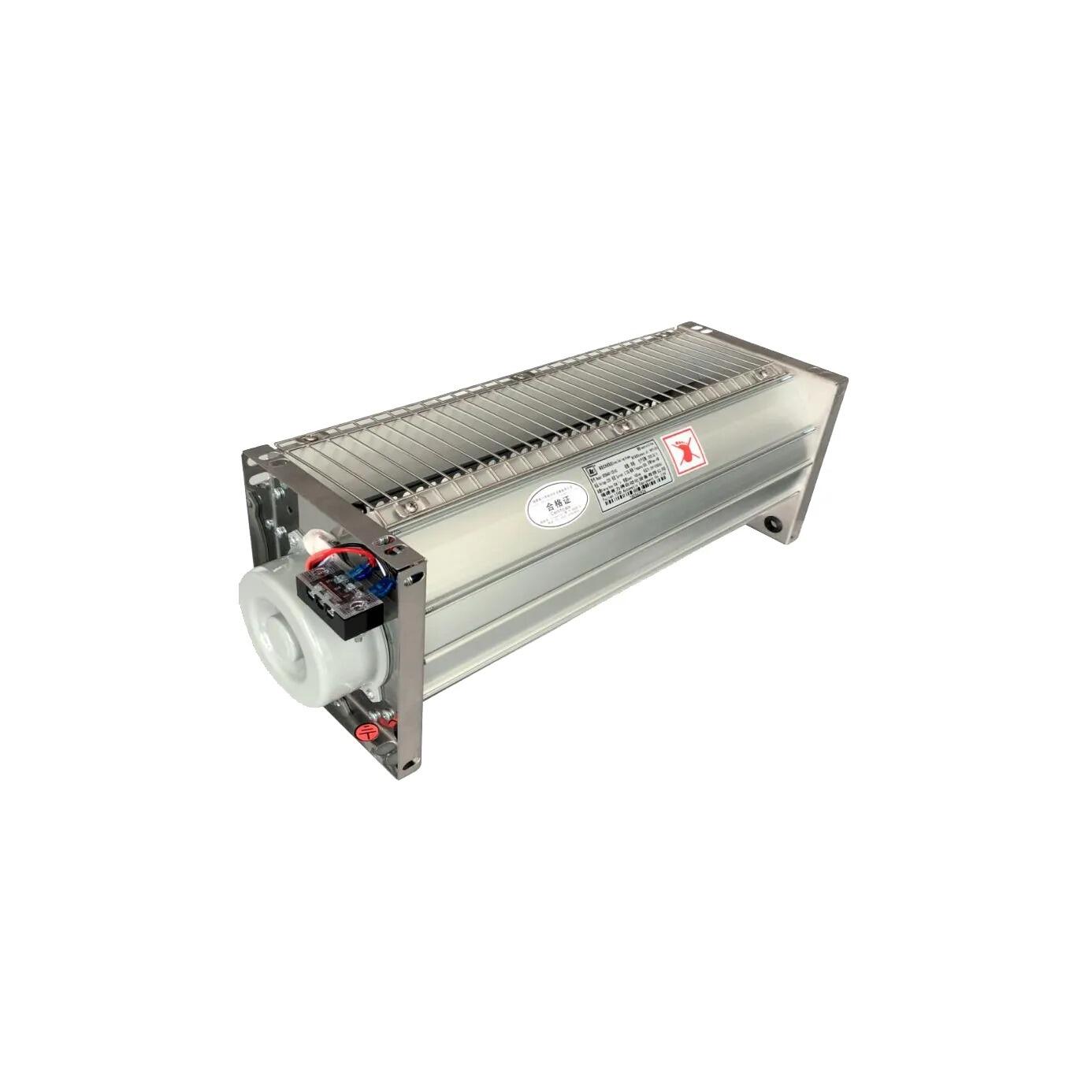
Wentylatory przepływowe poprzeczne, znane również jako wentylatory styczne lub transwersalne, generują przepływ powietrza za pomocą cylindrycznego wirnika, który tworzy ruch powietrza prostopadły do osi obrotu, wytwarzając szerokie, jednolite zasłony powietrza – idealne do chłodzenia powierzchni transformatorów suchych. W przeciwieństwie do wentylatorów odśrodkowych, w których powietrze wpływa wzdłuż osi i wypływa promieniowo, wentylatory przepływowe poprzeczne pobierają powietrze z jednej strony cylindrycznego wirnika i odprowadzają je po przeciwległej stronie, tworząc charakterystyczny prostokątny kształt przepływu powietrza. Ta konstrukcja generuje stosunkowo niskie ciśnienie statyczne, ale zapewnia doskonałą dystrybucję przepływu powietrza na rozległych powierzchniach, dzięki czemu wentylatory przepływowe poprzeczne są szczególnie skuteczne w chłodzeniu płaskich powierzchni uzwojeń charakterystycznych dla suchych transformatorów z żywicą odlewową oraz konstrukcji suchych transformatorów z wentylacją otwartą. Kształt przepływu powietrza naturalnie dopasowuje się do prostokątnej geometrii zespołów cewek transformatora, zapewniając efektywne odprowadzanie ciepła bez konieczności stosowania skomplikowanych układów kanałów wentylacyjnych lub systemów rozprowadzania przepływu.
Charakterystyka eksploatacyjna wentylatorów przepływowych w poprzek kierunku przepływu dobrze odpowiada wymogom chłodzenia wielu konfiguracji transformatorów suchych. Wentylatory te zazwyczaj pracują z niższą prędkością obrotową niż jednostki odśrodkowe, co skutkuje obniżeniem poziomu emisji akustycznych – cecha korzystna przy instalacjach w środowiskach wrażliwych na hałas, takich jak budynki biurowe, szpitale oraz obiekty edukacyjne. Rozszerzone otwory wylotowe wentylatorów przepływowych w poprzek kierunku przepływu powodują niższą prędkość powietrza wylotowego w porównaniu do skoncentrowanych wzorów wylotu charakterystycznych dla konstrukcji odśrodkowych, co zmniejsza hałas powietrza przy jednoczesnym zapewnieniu wystarczającej wymiany ciepła przez konwekcję. W przypadku transformatorów suchych chłodzonych naturalnie, ale z dodatkowym wymuszonym przepływem powietrza, wentylatory przepływowe w poprzek kierunku przepływu zapewniają łagodny przepływ powietrza, który wspomaga cyrkulację napędzaną siłą wyporu bez wywoływania nadmiernych zawirowań, które mogłyby faktycznie obniżyć skuteczność chłodzenia poprzez zakłócanie ustalonych wzorów konwekcji. Dlatego też są one szczególnie odpowiednie dla transformatorów suchych zaprojektowanych z uzupełniającym chłodzeniem sterowanym temperaturą, w którym wentylatory uruchamiane są wyłącznie w okresach podwyższonego obciążenia termicznego.
Zastosowania wentylatorów przepływowych
Wentylatory przepływowe wyróżniają się w zastosowaniach transformatorów suchych, gdzie priorytetem jest jednolite rozprowadzanie strumienia powietrza na dużych powierzchniach, a nie wysoka zdolność do generowania ciśnienia statycznego. Transformator suchy o otwartej wentylacji z wystającymi powierzchniami uzwojeń korzysta z szerokiego i równomiernego „zawieszonego” strumienia powietrza, który naturalnie wytwarzają wentylatory przepływowe, zapewniając skuteczne chłodzenie wszystkich sekcji uzwojeń bez powstawania gorących miejsc. W transformatorach suchych z zalanej żywicą epoksydową, których uzwojenia są całkowicie otoczone twardą powłoką z żywicy epoksydowej, powierzchnie chłodzące mają praktycznie płaski kształt, co czyni prostokątny kształt strumienia wyjściowego wentylatorów przepływowych idealnym rozwiązaniem zapewniającym optymalny kontakt termiczny. W instalacjach komercyjnych transformatorów suchych w pomieszczeniach zamkniętych, gdzie jakość akustyczna ma istotny wpływ na komfort użytkowników, często stosuje się wentylatory przepływowe, aby osiągnąć wymaganą wydajność chłodzenia przy jednoczesnym utrzymaniu poziomu hałasu poniżej 60 dBA w odległości jednego metra.
Fizyczna integracja wentylatorów przepływowych z obudowami transformatorów suchych zapewnia konkretne zalety projektowe. Długi i wąski kształt wentylatorów przepływowych umożliwia ich montaż na całej wysokości lub szerokości szaf transformatorowych, co zapewnia jednolity przepływ powietrza przez całą powierzchnię chłodzenia bez konieczności stosowania wielu oddzielnych jednostek wentylacyjnych. Uproszcza to instalację, zmniejsza liczbę komponentów oraz poprawia niezawodność w porównaniu z układami mniejszych wentylatorów odśrodkowych. Dla transformatorów suchych o ograniczonej głębokości, ale większej szerokości wentylatory przepływowe stanowią wydajne rozwiązanie pakunkowe dopasowane do geometrii transformatora. Modułowe systemy transformatorów suchych korzystają ze skalowalności konstrukcji wentylatorów przepływowych, ponieważ długość wentylatora może być dostosowana do wymiarów transformatora bez utraty wydajności. Właściwości te czynią wentylatory przepływowe szczególnie odpowiednimi dla niskoprofilowych transformatorów rozdzielczych suchych, wnętrzowych komercyjnych stacji transformatorowych oraz innych zastosowań, w których kluczowymi kryteriami wyboru są geometria instalacji oraz parametry akustyczne.
Systematyczny proces doboru wentylatorów
Obliczanie wymaganego przepływu powietrza
Podstawowym krokiem w doborze wentylatorów do chłodzenia transformatorów suchych jest obliczenie objętościowego przepływu powietrza niezbędnego do odprowadzenia wytworzonego ciepła przy jednoczesnym utrzymaniu dopuszczalnego wzrostu temperatury. Podstawowe równanie bilansu cieplnego wiąże rozpraszanie ciepła z objętościowym przepływem powietrza oraz różnicą temperatur zgodnie ze wzorem: Q = 1,2 × V × ΔT, gdzie Q oznacza obciążenie cieplne w watach, V – objętościowy przepływ powietrza w metrach sześciennych na sekundę, ΔT – wzrost temperatury w stopniach Celsjusza, a współczynnik 1,2 przybliża objętościową pojemność cieplną powietrza wynoszącą 1,2 kilodżuli na metr sześcienny na stopień Celsjusza. Dla suchego transformatora o mocy znamionowej 2000 kVA z całkowitymi stratami wynoszącymi 25 kW oraz zaprojektowanym wzrostem temperatury o 30 °C powyżej temperatury otoczenia wymagany przepływ powietrza wynosi około 0,69 metra sześciennego na sekundę, czyli 2500 metrów sześciennych na godzinę.
To obliczone wymaganie przepływu powietrza należy dostosować do rzeczywistych warunków eksploatacji wpływających na wydajność cieplną suchego transformatora. Korekty związane z wysokością nad poziomem morza uwzględniają zmniejszoną gęstość powietrza na terenach położonych powyżej poziomu morza, co wymaga zwiększenia przepływu powietrza o około dziesięć procent na każdy tysiąc metrów wysokości, aby zachować równoważne wartości masowego przepływu. W środowiskach o wysokiej temperaturze otoczenia konieczne jest zwiększenie przepływu powietrza w celu osiągnięcia tych samych bezwzględnych temperatur uzwojeń; szczególnie staranne rozważania są wymagane w przypadku, gdy temperatura otoczenia zbliża się do 40 °C lub przekracza tę wartość, ponieważ w takich warunkach standardowe moc znamionowa suchych transformatorów może wymagać obniżenia. Rozważania dotyczące współczynnika obciążenia decydują o tym, czy wymagana jest ciągła maksymalna zdolność przepływu powietrza, czy też wystarczająca jest obsługa sterowana temperaturą przy niższym średnim przepływie powietrza, spełniająca potrzeby zarządzania ciepłem. Marginesy bezpieczeństwa zazwyczaj zwiększają obliczone wymagania przepływu powietrza o piętnaście–dwadzieścia pięć procent, aby uwzględnić niepewności związane z oporem układu, degradację wydajności wentylatorów w czasie oraz potencjalne przyszłe wzrosty obciążenia suchego transformatora.
Określenie oporu systemu i punktu pracy
Dokładne określenie oporu systemu przepływu powietrza jest kluczowe dla właściwego wyboru wentylatora, ponieważ niedocenianie oporu prowadzi do niewystarczającego chłodzenia, a nadocenianie prowadzi do niepotrzebnego zużycia energii i hałasu. Oporność systemu obejmuje wszystkie spadki ciśnienia w drodze przepływu powietrza, w tym siatki wpustowe, elementy filtrów, przejścia zwojowe transformatora, kanały wentylacyjne, zmiany kierunku i żaluzje wyjściowe. Każdy składnik przyczynia się do oporu proporcjonalnego do kwadratu prędkości powietrza, tworząc krzywą oporu systemu parabolicznego, gdy jest wykreowany na podstawie objętościowej przepływu. W przypadku typowych instalacji suchych transformatorów ograniczenia wjazdowe i wyjściowe mogą stanowić 30-40% całkowitego oporu systemu, opór rdzenia transformatora 20-30%, a pozostałe - kanały i wyposażenie.
Punkt pracy pojawia się tam, gdzie wybrana krzywa charakterystyki wentylatora przecina obliczoną krzywą oporu układu, określając rzeczywistą przepływaną objętość powietrza oraz pobieraną moc. Ten punkt przecięcia powinien idealnie znajdować się w zakresie od czterdziestu do siedemdziesięciu procent maksymalnej wydajności przepływowej wentylatora, aby zapewnić stabilną pracę i akceptowalną sprawność. Punkty pracy leżące zbyt daleko po lewej stronie krzywej wentylatora mogą prowadzić do niestabilności i nadmiernego hałasu, podczas gdy punkty położone zbyt daleko po prawej stronie wskazują na niewystarczającą zdolność ciśnieniową oraz potencjalną niemożność pokonania zmian oporu układu. W zastosowaniach do transformatorów suchych punkt pracy należy zweryfikować w odniesieniu do minimalnie wymaganej objętości przepływu powietrza, obliczonej na podstawie rozważań termicznych, co potwierdza wystarczający zapas chłodzenia. W przypadku układów z wieloma wentylatorami konieczna jest staranna analiza zapewniająca stabilność pracy równoległej; krzywe charakterystyk poszczególnych wentylatorów należy poprawnie zsumować, a w projektowaniu układu należy uwzględnić możliwość nierównomiernego rozdziału przepływu.
Wymagania dotyczące integracji elektrycznej i sterowania
Interfejs elektryczny pomiędzy wentylatorami chłodzącymi a systemami sterowania transformatorami suchymi wymaga starannego określenia, aby zapewnić niezawodne działanie oraz prawidłową koordynację z systemami ochrony transformatorów. Silniki wentylatorów muszą być przystosowane do pracy ciągłej przy napięciu zasilania dostępnym w miejscu instalacji, zwykle 220 V jednofazowe lub 380 V trójfazowe, w zależności od wymagań mocy wentylatorów oraz lokalnych norm elektrycznych. Charakterystyki prądu rozruchowego należy ocenić w odniesieniu do dostępnej pojemności obwodu, z szczególnym uwzględnieniem prądów udarowych przy bezpośrednim rozruchu (DOL) lub określeniem urządzeń łagodnego rozruchu dla większych silników wentylatorów. Wszystkie silniki wentylatorów muszą być wyposażone w zabezpieczenie przed przeciążeniem termicznym, przy czym styki wyzwalające powinny być zintegrowane z systemem monitoringu transformatora suchego, aby ostrzegać operatorów o awariach systemu chłodzenia, które mogą prowadzić do nadmiernego nagrzewania się transformatora.
Systemy chłodzenia z regulacją temperatury wymagają zsynchronizowanej integracji między czujnikami cieplnymi transformatora a obwodami sterowania wentylatorami. Detektory oporowe temperatury lub termistory wbudowane w uzwojenia suchych transformatorów dostarczają sygnałów zwrotnych dotyczących temperatury do przekaźników sterujących lub programowalnych sterowników logicznych, które aktywują wentylatory chłodzące po przekroczeniu ustalonych progów. Typowe schematy sterowania aktywują wentylatory, gdy temperatura uzwojeń osiągnie zakres od 80°C do 100°C, zapewniając zarządzanie ciepłem przy obciążeniach wysokich, a jednocześnie pozwalając na chłodzenie przez konwekcję naturalną przy niskim obciążeniu. W logice sterowania należy zastosować histerezę, aby zapobiec szybkiemu cyklowaniu wentylatorów – zwykle wentylatory pozostają w stanie pracy, dopóki temperatura nie spadnie o 10°C–15°C poniżej punktu aktywacji. Zaawansowane systemy mogą implementować wiele etapów temperatury z odpowiadającymi im poziomami prędkości wentylatorów, co optymalizuje wydajność energetyczną i jednocześnie gwarantuje wystarczającą zdolność chłodzenia we wszystkich warunkach eksploatacyjnych występujących w przypadku suchych transformatorów.
Weryfikacja i optymalizacja wydajności
Procedury uruchamiania i testy cieplne
Poprawne uruchomienie systemów chłodzenia transformatorów suchych potwierdza, że wybrane wentylatory zapewniają wydajność zgodną z projektem oraz że pełny system zarządzania ciepłem utrzymuje temperatury w dopuszczalnych granicach. Początkowe badania powinny potwierdzić rzeczywistą wydajność przepływu powietrza poprzez pomiar prędkości powietrza w wielu punktach na otworach dopływowych i odpływowych przy użyciu skalibrowanych anemometrów lub rurek Pitota oraz porównanie całkowitego zmierzonego przepływu z wymaganiami projektowymi. Pomiar ciśnienia statycznego w miejscu odpływu wentylatora oraz na wlocie do transformatora pozwala zweryfikować, czy krzywa oporów układu zgadza się z obliczeniami projektowymi oraz czy wentylatory pracują w zamierzonym punkcie na swoich charakterystykach wydajnościowych. Te pomiary podstawowe stanowią dane odniesienia dotyczące wydajności, które będą wykorzystywane w przyszłości do porównań podczas czynności konserwacyjnych oraz procedur diagnostycznych.
Testy wydajności cieplnej wykazują, że system chłodzenia utrzymuje temperatury transformatora suchego w granicach dopuszczalnych przy rzeczywistych warunkach eksploatacji. Monitorowanie temperatury podczas kontrolowanej sekwencji obciążania – od stanu bez obciążenia przez obciążenie znamionowe po krótkotrwałą zdolność do przekroczenia obciążenia – potwierdza wystarczającą skuteczność chłodzenia we wszystkich punktach pracy. Wskaźniki temperatury uzwojeń oraz wbudowane czujniki termiczne należy monitorować w sposób ciągły podczas testów nagrzewania, które zwykle przeprowadza się w okresie stabilizacji trwającym od czterech do sześciu godzin przy każdym poziomie obciążenia. Kryteria akceptacji powinny potwierdzać, że ustalone temperatury uzwojeń pozostają w granicach klas izolacji F lub H z odpowiednimi marginesami bezpieczeństwa, co zwykle oznacza utrzymanie temperatury punktów najgorętszych co najmniej o 10 °C poniżej maksymalnych wartości dopuszczalnych w trybie ciągłym. Termowizja podczerwieni może uzupełnić odczyty wbudowanych czujników, umożliwiając wykrycie ewentualnych lokalnych obszarów przegrzania, które mogą wskazywać na niewystarczające rozprowadzenie strumienia powietrza lub zablokowane kanały wentylacyjne wymagające korekty.
Właściwości akustyczne i kontrola hałasu
Emisja dźwięku przez wentylatory chłodzące transformatory suchego typu często stanowi istotny czynnik przy ich instalacji, szczególnie w przypadku zastosowań komercyjnych i instytucjonalnych w pomieszczeniach zamkniętych, gdzie konieczne jest spełnienie norm komfortu użytkowników. Hałas generowany przez wentylatory składa się z hałasu aerodynamicznego powstającego wskutek turbulencji przepływu powietrza oraz hałasu mechanicznego pochodzącego z pracy silnika i łożysk; całkowite poziomy ciśnienia akustycznego mieszczą się zwykle w zakresie od 55 do 75 dBA w odległości jednego metra od wentylatora, w zależności od typu, rozmiaru i prędkości obrotowej wentylatora. Wentylatory poprzeczne wytwarzają zazwyczaj niższe poziomy hałasu niż wentylatory odśrodkowe o tej samej wydajności, co wynika z niższych prędkości obrotowych i mniejszej turbulencji powietrza. Pomiary poziomu dźwięku należy przeprowadzać w określonych odległościach i kierunkach wokół instalacji transformatora suchego, porównując uzyskane wyniki z obowiązującymi kryteriami hałasu, takimi jak normy NEMA lub lokalne przepisy budowlane.
Strategie ograniczania hałasu mogą zmniejszać wpływ akustyczny, gdy mierzone poziomy dźwięku przekraczają dopuszczalne granice. Obniżenie prędkości obrotowej wentylatora poprzez zmianę przełożenia przekładni lub zastosowanie falowników umożliwia znaczne zmniejszenie poziomu hałasu – poziom ciśnienia akustycznego spada o około 15 dBA przy każdej redukcji prędkości obrotowej o 50%, choć przepustowość powietrza maleje proporcjonalnie. Obudowy akustyczne lub bariera akustyczna wokół miejsc montażu wentylatorów zapewniają tłumienie w zakresie od 10 do 20 dBA, pod warunkiem ich prawidłowego zaprojektowania z wykorzystaniem materiałów pochłaniających dźwięk wewnątrz oraz minimalizacji ścieżek omijających. Tłumiki na przewodach dopływowych i odpływowych, wyposażone w przegrody akustyczne, ograniczają transmisję hałasu powietrzem, jednak zwiększają opór układu, który należy uwzględnić przy doborze wentylatora. W przypadku instalacji transformatorów suchych w środowiskach szczególnie wrażliwych na hałas określenie specyfikacji wysokiej klasy, niskoszczelnych modeli wentylatorów zaprojektowanych z uwzględnieniem optymalizacji akustycznej może okazać się bardziej opłacalne niż próba ograniczenia hałasu generowanego przez standardowe wentylatory przemysłowe za pomocą dodatkowych środków korekcyjnych.
Zważywania dotyczące efektywności energetycznej
Zużycie energii przez wentylatory chłodzące stanowi ciągłe koszty eksploatacyjne, które należy uwzględnić w trakcie procesu doboru, szczególnie w przypadku dużych transformatorów suchych wymagających ciągłego chłodzenia powietrzem wymuszonym. Moc silników wentylatorów zwykle mieści się w zakresie od 0,3 do 2,0 procenta mocy znamionowej transformatora wyrażonej w kVA, w zależności od projektu i efektywności systemu chłodzenia, co przekłada się na kilka kilowatów ciągłego zużycia energii w przypadku transformatorów suchych średniej i dużej mocy. Roczne koszty energii można obliczyć, mnożąc moc wentylatorów przez liczbę godzin pracy w ciągu roku oraz lokalne stawki za energię elektryczną; przy ciągłej eksploatacji w warunkach przemysłowych koszty te mogą wynosić kilka tysięcy dolarów rocznie dla większych instalacji. Sterowanie pracą wentylatorów w oparciu o temperaturę zmniejsza zużycie energii proporcjonalnie do rzeczywistego czasu ich działania, co często pozwala osiągnąć oszczędności energii w zakresie od trzydziestu do pięćdziesięciu procent w porównaniu z trybem pracy ciągłej w przypadku transformatorów suchych o zmiennej charakterystyce obciążenia.
Sprawność wentylatora ma istotny wpływ na koszty eksploatacji w trakcie kilkudziesięcioletniego okresu użytkowania charakterystycznego dla instalacji transformatorów suchych. Silniki o podwyższonej sprawności spełniające międzynarodowe normy IE3 lub IE4 mogą wiązać się z umiarkowanym wzrostem początkowych kosztów inwestycyjnych, ale zapewniają znaczne oszczędności w całym okresie użytkowania dzięki zmniejszeniu strat elektrycznych. Jakość aerodynamicznego projektu wentylatora wpływa na ogólną sprawność systemu – dobrze zaprojektowane wentylatory odśrodkowe lub przepływowe osiągają łączną sprawność w zakresie 40–60% przy przekształcaniu mocy wału silnika w użyteczną przepływową moc powietrza. Sterowniki częstotliwościowe umożliwiają dopasowanie prędkości obrotowej wentylatora do rzeczywistego zapotrzebowania chłodniczego, co potencjalnie pozwala zmniejszyć zużycie energii o 30–40% w porównaniu z pracą przy stałej prędkości obrotowej, a jednocześnie obniża emisję hałasu w okresach zmniejszonego obciążenia cieplnego. Analiza kosztów cyklu życia, uwzględniająca początkową cenę wyposażenia, prognozowane koszty energii oraz wymagania serwisowe w typowym 20–30-letnim okresie użytkowania transformatora suchego, stanowi najbardziej kompleksową podstawę decyzji dotyczących wyboru wentylatora, gdy efektywność energetyczna jest istotnym kryterium oceny.
Często zadawane pytania
Jaka jest typowa żywotność wentylatorów chłodzących stosowanych w transformatorach suchych?
Ventylatory chłodzące do zastosowań w transformatorach suchych osiągają zwykle czas pracy od 50 000 do 100 000 godzin, w zależności od jakości konstrukcji, warunków eksploatacji oraz praktyk konserwacyjnych, co odpowiada przybliżonie 10–20 latom ciągłej pracy. Wysokiej klasy przemysłowe wentylatory z uszczelnionymi łożyskami kulkowymi lub konstrukcjami nie wymagającymi konserwacji mogą przekraczać te zakresy, podczas gdy wentylatory pracujące w trudnych warunkach środowiskowych – np. przy skrajnych temperaturach, zanieczyszczeniach lub przy niewłaściwej konserwacji – mogą mieć krótszy okres użytkowania. Regularna konserwacja, obejmująca smarowanie łożysk, kontrolę silnika oraz czyszczenie nagromadzonego brudu, wydłuża żywotność wentylatorów i zapewnia utrzymanie ich wydajności przez cały okres eksploatacji transformatora suchego.
Czy istniejące wentylatory chłodzące można zmodernizować (dostosować), jeśli transformator suchy zostanie przeznaczony do pracy przy wyższej mocy lub przeniesiony do środowiska o wyższej temperaturze otoczenia?
Istniejące wentylatory chłodzące można czasem zainstalować w istniejącym transformatorze lub uzupełnić je dodatkowymi jednostkami w przypadku wzrostu obciążenia transformatora suchego lub zmian warunków otoczenia, choć wymagana jest staranna analiza inżynierska potwierdzająca ich wystarczającą skuteczność. Jeśli pierwotny system chłodzenia zawiera zapas mocy, umiarkowany wzrost obciążenia o dziesięć do piętnastu procent może być obsłużony bez konieczności wprowadzania modyfikacji. Istotniejsze zmiany zwykle wymagają dodania wentylatorów pomocniczych, wymiany istniejących jednostek na modele o wyższej wydajności lub wdrożenia sterowania prędkością obrotową zmienną w celu maksymalnego wykorzystania możliwości istniejącego sprzętu. Przed wprowadzeniem jakichkolwiek modyfikacji w systemie chłodzenia należy skonsultować się z producentem transformatora, aby upewnić się, że zaproponowane zmiany zapewnią utrzymanie temperatur w granicach dopuszczalnych i zachowanie ważności gwarancji.
W jaki sposób wentylatory odśrodkowe i przepływowe porównują się pod względem wymagań serwisowych w zastosowaniach chłodzenia transformatorów suchych?
Wentylatory odśrodkowe i przepływowe mają porównywalne wymagania serwisowe; oba typy zwykle wymagają okresowych przeglądów, czyszczenia, smarowania łożysk (jeśli są one smarowane) oraz ostatecznej wymiany silnika lub łożysk po wielu latach eksploatacji. Wentylatory odśrodkowe z łopatkami zakrzywionymi do tyłu lub w kształcie profilu aerodynamicznego mogą gromadzić mniej pyłu i zanieczyszczeń niż modele z łopatkami zakrzywionymi do przodu, co potencjalnie wydłuża interwały między czyszczeniami. Wentylatory przepływowe z wydłużonymi, cylindrycznymi wirnikami mogą czasem być nieco trudniejsze w dokładnym oczyszczeniu w porównaniu do kół wentylatorów odśrodkowych, choć ich niższe prędkości obrotowe mogą zmniejszać tempo zużycia łożysk. Oba typy wentylatorów korzystają z corocznych harmonogramów przeglądów obejmujących monitorowanie drgań, weryfikację połączeń elektrycznych oraz sprawdzanie wydajności przepływu powietrza, aby wykryć powstające problemy jeszcze przed wystąpieniem awarii układu chłodzenia wpływających na pracę suchego transformatora.
Jakie zagadnienia bezpieczeństwa należy uwzględnić podczas pracy przy wentylatorach chłodzących suche transformatory lub w ich pobliżu podczas ich działania?
Prace wykonywane na wentylatorach chłodzących działającego transformatora suchego lub w ich pobliżu wymagają szczególnej uwagi ze względu na zagrożenia elektryczne, mechaniczne oraz termiczne. Wszelkie konserwacje wentylatorów powinny być – o ile to możliwe – wykonywane przy odłączeniu zasilania transformatora suchego i zablokowaniu wentylatorów chłodzących zgodnie z obowiązującymi procedurami bezpieczeństwa elektrycznego. Jeśli kontrola musi zostać przeprowadzona podczas pracy urządzenia, pracownicy muszą zachować bezpieczne odległości od wirujących elementów, zapewnić, że wszystkie osłony i pokrywy ochronne pozostają na swoim miejscu, oraz unikać luźnej odzieży lub materiałów, które mogłyby zostać wciągnięte do przewietrzników wentylatorów. Podwyższone temperatury występujące wokół działających transformatorów suchych stwarzają zagrożenia termiczne, wymagające stosowania odpowiednich środków ochrony indywidualnej; ryzyko porażenia prądem wynikające z wystawionych zacisków i obwodów sterowania wymaga zaangażowania wykwalifikowanego personelu oraz przestrzegania obowiązujących norm bezpieczeństwa elektrycznego we wszystkich czynnościach związanych z konserwacją systemu chłodzenia.
Spis treści
- Zrozumienie transformatorów suchych Transformator Potrzeb chłodzenia
- Metodologia doboru wentylatorów odśrodkowych
- Metodologia doboru wentylatorów przepływowych
- Systematyczny proces doboru wentylatorów
- Weryfikacja i optymalizacja wydajności
-
Często zadawane pytania
- Jaka jest typowa żywotność wentylatorów chłodzących stosowanych w transformatorach suchych?
- Czy istniejące wentylatory chłodzące można zmodernizować (dostosować), jeśli transformator suchy zostanie przeznaczony do pracy przy wyższej mocy lub przeniesiony do środowiska o wyższej temperaturze otoczenia?
- W jaki sposób wentylatory odśrodkowe i przepływowe porównują się pod względem wymagań serwisowych w zastosowaniach chłodzenia transformatorów suchych?
- Jakie zagadnienia bezpieczeństwa należy uwzględnić podczas pracy przy wentylatorach chłodzących suche transformatory lub w ich pobliżu podczas ich działania?