Selecting the appropriate cooling solution for dry-type transformers represents a critical engineering decision that directly impacts equipment performance, operational efficiency, and long-term reliability. Among the most widely deployed forced air cooling technologies, centrifugal fans and cross-flow fans serve distinct roles in transformer thermal management systems. Understanding the fundamental differences between these two fan architectures, their respective performance characteristics, and the specific application scenarios where each excels enables engineers and facility managers to make informed decisions that optimize cooling effectiveness while controlling energy consumption and maintenance requirements.
Dry-type transformers require forced air cooling systems to maintain safe operating temperatures, particularly under high load conditions or in environments with elevated ambient temperatures. The choice between centrifugal fan technology and cross-flow fan design fundamentally affects airflow distribution patterns, static pressure capabilities, noise generation, space utilization, and installation flexibility. This comprehensive selection guide examines the core engineering differences between these two fan types, analyzes their respective advantages and limitations in transformer cooling applications, and provides practical decision criteria to help you determine which technology best aligns with your specific operational requirements and installation constraints.
Fundamental Operating Principles and Design Architecture
Centrifugal Fan Airflow Mechanics and Structural Configuration
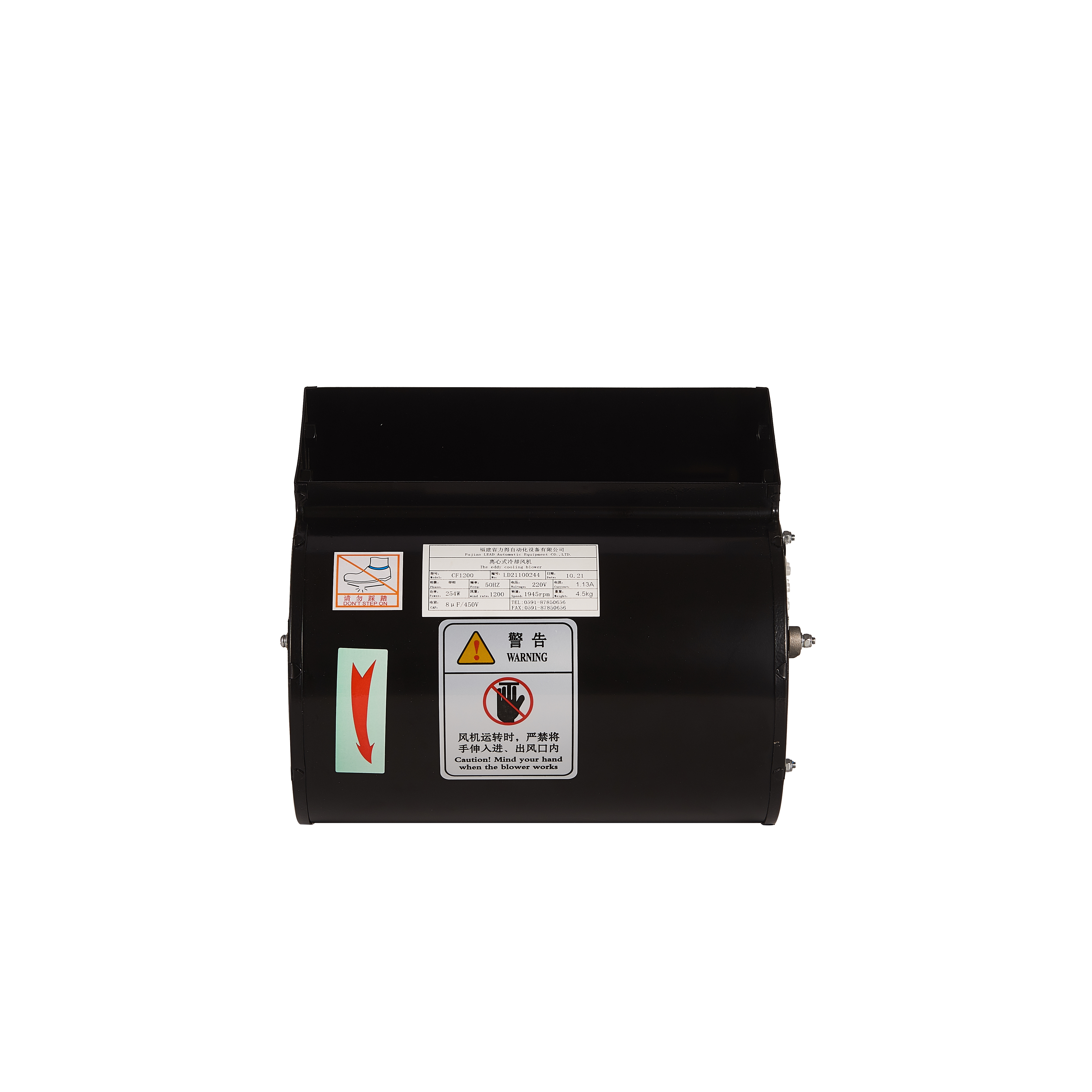
The centrifugal fan operates through a radial airflow principle where air enters axially through the fan inlet and is redirected perpendicular to the rotational axis through centrifugal force generated by the impeller blades. This design architecture features a scroll-shaped housing that collects and directs the accelerated air into a focused discharge stream. The impeller consists of multiple backward-curved, forward-curved, or radial blades mounted on a central hub, with blade geometry significantly influencing pressure development and efficiency characteristics. When the impeller rotates, air particles experience centrifugal acceleration, moving radially outward from the impeller eye to the blade tips where kinetic energy converts to static pressure within the volute casing.
This fundamental operating mechanism enables centrifugal fan designs to generate substantially higher static pressure compared to axial-flow alternatives, making them particularly effective in applications requiring air delivery through restrictive pathways or against significant system resistance. The compact footprint relative to airflow capacity, combined with the ability to efficiently handle varying back-pressure conditions, positions centrifugal fan technology as a preferred solution for dry-type transformer installations where space constraints exist or where air must be directed through heat exchanger cores, ductwork, or confined cooling channels. The centrifugal fan architecture also provides flexibility in discharge orientation, allowing engineers to configure airflow direction to match specific transformer enclosure geometries.
Cross-Flow Fan Operation and Structural Characteristics
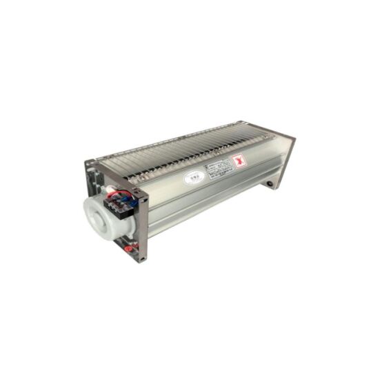
Cross-flow fans, also known as tangential fans or transverse fans, employ a distinctly different airflow mechanism where air enters and exits the impeller at perpendicular orientations relative to the rotational axis. The cylindrical impeller features numerous forward-curved blades arranged around the circumference, creating an elongated air passage that produces a uniform, wide discharge pattern along the entire impeller length. Air enters tangentially on one side of the rotating cylinder, flows through the blade passages crossing the impeller diameter, and exits tangentially on the opposite side, generating a flat, sheet-like airflow profile that extends across the full axial dimension of the fan assembly.
This unique airflow topology makes cross-flow fan designs particularly effective for applications requiring uniform air distribution across extended surface areas, such as the vertical cooling surfaces of dry-type transformer windings. The elongated discharge pattern eliminates the concentrated airflow characteristics typical of centrifugal fan installations, reducing thermal gradients and hotspot formation across transformer cooling surfaces. Cross-flow fan assemblies integrate seamlessly into slim profile enclosures, with the fan motor and impeller occupying minimal depth while delivering airflow across substantial width dimensions. However, the cross-flow fan architecture inherently generates lower static pressure capability compared to centrifugal fan technology, limiting effectiveness in applications with significant airflow resistance or requiring air delivery through restrictive passages.
Comparative Pressure-Flow Performance Characteristics
The pressure-flow performance curves for centrifugal fan and cross-flow fan technologies reveal fundamental differences that directly influence suitability for specific dry-type transformer cooling scenarios. Centrifugal fan designs typically deliver maximum static pressure ranging from 100 to 600 Pascals depending on impeller diameter, rotational speed, and blade configuration, with backward-curved blade designs offering optimal efficiency across broad operating ranges. This substantial pressure development capability enables centrifugal fan installations to overcome system resistance created by heat exchanger fins, air filters, ductwork transitions, and confined ventilation pathways while maintaining adequate volumetric airflow to meet transformer cooling requirements.
Cross-flow fan assemblies generate comparatively modest static pressure, typically ranging from 20 to 80 Pascals in standard transformer cooling configurations. This lower pressure capability restricts cross-flow fan applications to installations with minimal airflow resistance, such as open-frame transformer designs or enclosures with large, unobstructed ventilation openings. The trade-off for reduced pressure development is exceptional uniformity in airflow distribution, with cross-flow fan technology delivering consistent air velocity across 80-95% of the discharge width compared to 40-60% uniformity typical of centrifugal fan installations. For transformer cooling applications where uniform temperature distribution across winding surfaces represents the primary objective, cross-flow fan technology offers distinct advantages despite lower pressure capability.
Practical Application Scenarios and Installation Considerations
Centrifugal Fan Applications in Transformer Cooling Systems
Centrifugal fan technology demonstrates optimal performance in dry-type transformer installations requiring high-pressure air delivery, compact mounting configurations, or directed airflow through specific cooling pathways. Large capacity transformers with integrated heat exchanger systems rely extensively on centrifugal fan assemblies to force cooling air through finned aluminum or copper heat sink arrays, where the elevated static pressure capability ensures adequate airflow penetration through the closely-spaced fin geometry. Industrial facilities housing multiple transformers in dedicated electrical rooms commonly employ centrifugal fan systems with ductwork distribution networks, leveraging the pressure development characteristics to deliver conditioned cooling air from remote air handling units to individual transformer locations.
Outdoor transformer installations exposed to harsh environmental conditions benefit from centrifugal fan technology through the ability to integrate protective inlet filtration without compromising cooling performance. The pressure reserve inherent in centrifugal fan designs compensates for filter pressure drop while maintaining required airflow rates, extending maintenance intervals and protecting internal transformer components from particulate contamination. Mining operations, heavy manufacturing facilities, and coastal installations where airborne contaminants present significant concerns particularly value this capability. Additionally, retrofit applications upgrading natural convection transformers to forced air cooling frequently specify centrifugal fan assemblies due to mounting flexibility and minimal modifications required to existing transformer enclosures.
Cross-Flow Fan Suitability for Specific Transformer Configurations
Cross-flow fan installations excel in dry-type transformer applications prioritizing uniform cooling distribution, minimal acoustic signature, and slim-profile enclosure designs. Medium voltage cast resin transformers with vertical winding configurations particularly benefit from cross-flow fan technology, where the elongated discharge pattern delivers consistent airflow across the full winding height, eliminating thermal stratification and reducing peak winding temperatures. Transformer installations in commercial buildings, healthcare facilities, and educational institutions where noise control represents a critical design parameter frequently specify cross-flow fan systems due to inherently lower acoustic output compared to equivalent capacity centrifugal fan assemblies operating at similar volumetric flow rates.
Open-ventilated transformer designs without restrictive enclosures or filtration systems represent ideal applications for cross-flow fan technology, allowing the fans to operate within their optimal low-resistance performance envelope. Substation transformers installed in dedicated outdoor compounds with substantial clearance around equipment perimeters commonly employ cross-flow fan arrays mounted along transformer sidewalls, creating curtains of cooling air that bathe winding surfaces uniformly while operating at reduced rotational speeds that minimize energy consumption and extend bearing service life. The modular nature of cross-flow fan assemblies also facilitates scalable cooling capacity, enabling engineers to adjust the number of fan modules to precisely match transformer thermal load requirements without oversizing individual fan components.
Installation Space Requirements and Mounting Configurations
Physical space constraints within transformer enclosures or electrical rooms significantly influence the practical selection between centrifugal fan and cross-flow fan technologies. Centrifugal fan assemblies require adequate clearance surrounding the volute housing to accommodate air intake, discharge orientation, and motor mounting arrangements, with total installation depth typically ranging from 150mm to 400mm depending on fan capacity and performance specifications. However, the compact cross-sectional area of centrifugal fan designs enables installation in confined locations where mounting surface area is limited, such as transformer enclosure sidewalls or rooftop ventilation housings where vertical clearance constraints would preclude alternative fan technologies.
Cross-flow fan installations demand substantial mounting width corresponding to the impeller length required to deliver specified airflow rates, with standard transformer cooling modules ranging from 600mm to 1200mm in length. The shallow installation depth of cross-flow fan assemblies, typically 80mm to 150mm including motor and structural components, makes them ideal for slim-profile transformer enclosures where depth restrictions would eliminate centrifugal fan consideration. Transformer manufacturers increasingly integrate cross-flow fan technology directly into cast resin transformer structural frames, positioning fan modules between winding assemblies where the flat discharge profile provides optimal cooling efficiency without requiring separate fan housings or ductwork distribution systems that consume additional enclosure volume.
Performance Factors Influencing Selection Decisions
Thermal Efficiency and Temperature Distribution Characteristics
The thermal performance effectiveness of centrifugal fan and cross-flow fan installations in dry-type transformer cooling applications extends beyond simple volumetric airflow delivery to encompass airflow distribution uniformity, heat transfer coefficient optimization, and mitigation of localized thermal hotspots. Centrifugal fan systems generate concentrated, high-velocity airflow streams that effectively penetrate heat exchanger cores and confined cooling channels, maximizing convective heat transfer in targeted regions where thermal loads concentrate. This characteristic proves particularly valuable in transformer designs featuring integrated cooling ducts or heat sink arrays where directing airflow precisely through thermal management components ensures efficient heat extraction from critical winding locations.
Cross-flow fan installations deliver superior temperature uniformity across extended transformer surfaces, reducing peak winding temperature differentials by 8-15°C compared to equivalent capacity centrifugal fan systems in open-frame transformer configurations. This enhanced thermal distribution minimizes thermal stress on insulation materials, reduces hotspot-driven aging acceleration, and enables more aggressive transformer loading profiles within manufacturer temperature rise limits. Field measurements from cast resin transformer installations demonstrate that cross-flow fan technology consistently achieves temperature variations below 5°C across monitored winding locations, compared to 12-20°C variations typical of point-source centrifugal fan cooling, directly translating to improved insulation life expectancy and reduced failure risk from thermal cycling fatigue.
Acoustic Performance and Noise Control Considerations
Acoustic characteristics represent increasingly important selection criteria for transformer cooling systems, particularly in installations adjacent to occupied spaces or noise-sensitive environments where excessive fan noise creates operational complaints and regulatory compliance concerns. Centrifugal fan technology generates distinct acoustic signatures dominated by blade pass frequency tones and aerodynamic noise from air turbulence within the volute housing, with overall sound power levels typically ranging from 65 to 85 dBA at one meter distance depending on fan capacity, rotational speed, and impeller blade configuration. Backward-curved centrifugal fan designs incorporating aerodynamically optimized blade profiles and enlarged volute sections achieve noise reductions of 5-8 dBA compared to forward-curved or radial blade alternatives at equivalent airflow delivery rates.
Cross-flow fan assemblies inherently produce lower acoustic output compared to centrifugal fan installations of similar volumetric capacity, with typical sound power levels ranging from 55 to 70 dBA measured at one meter from the discharge plane. The distributed airflow generation mechanism and lower rotational speeds characteristic of cross-flow fan operation reduce both tonal noise components and broadband aerodynamic noise, creating a subjectively quieter acoustic signature that proves less intrusive in occupied environments. Transformer installations in commercial buildings, hospitals, and data centers increasingly specify cross-flow fan cooling systems specifically to meet stringent ambient noise limits, accepting modest performance trade-offs in pressure capability to achieve acoustic design targets that would require extensive silencing treatments if centrifugal fan technology were employed.
Energy Efficiency and Operational Cost Analysis
Lifecycle operational costs associated with transformer cooling systems encompass electrical energy consumption for fan operation, maintenance expenditures for component replacement, and indirect costs related to system reliability and availability. Centrifugal fan technology offers superior energy efficiency in high-resistance cooling applications where substantial static pressure development is required, with well-designed backward-curved centrifugal fan assemblies achieving total efficiency values of 65-80% when operating within their optimal performance range. The ability of centrifugal fan systems to maintain stable performance across varying system resistance conditions ensures consistent energy efficiency throughout the operational lifecycle, even as air filters load with particulate accumulation or heat exchanger surfaces experience minor fouling.
Cross-flow fan installations demonstrate exceptional energy efficiency in low-resistance cooling applications where their pressure capability limitations do not constrain performance, with motor input power requirements typically 20-30% lower than equivalent airflow capacity centrifugal fan systems in open-ventilated transformer configurations. However, the energy advantage of cross-flow fan technology diminishes rapidly as system resistance increases, with efficiency dropping precipitously when installations require operation against static pressure exceeding 40-50 Pascals. Engineers evaluating energy consumption over typical 20-25 year transformer service lives must carefully assess anticipated system resistance conditions, accounting for filter maintenance intervals, potential heat exchanger fouling, and ventilation pathway deterioration to accurately project comparative operational costs between centrifugal fan and cross-flow fan alternatives.
Reliability, Maintenance, and Service Life Factors
Mechanical Reliability and Component Durability
The mechanical reliability and service life expectations for centrifugal fan systems in dry-type transformer cooling applications depend primarily on bearing quality, impeller balance, motor selection, and environmental exposure conditions. Industrial-grade centrifugal fan assemblies employing sealed ball bearings with appropriate lubrication for the operating temperature range routinely achieve 50,000 to 80,000 hours of continuous operation before bearing replacement becomes necessary, translating to 8-12 years of service in typical transformer cooling duty cycles with 50-70% average runtime. Impeller construction materials significantly influence durability, with aluminum or steel impellers providing superior structural integrity compared to plastic alternatives in high-temperature environments where transformer enclosure temperatures may exceed 60°C during peak loading periods.
Cross-flow fan assemblies demonstrate comparable mechanical reliability when properly specified for transformer cooling environments, though the elongated impeller geometry and smaller bearing sizes characteristic of cross-flow fan designs necessitate careful attention to vibration control and mounting rigidity. Bearing service life in cross-flow fan installations typically ranges from 40,000 to 60,000 hours under continuous duty conditions, with actual service intervals heavily influenced by mounting orientation, vibration isolation effectiveness, and operating temperature exposure. The inherently balanced nature of cylindrical cross-flow fan impellers reduces dynamic loads on bearing systems compared to single-sided centrifugal fan impellers, potentially offsetting the bearing size disadvantage in applications where isolation mounting effectively minimizes external vibration transmission to fan components.
Maintenance Requirements and Serviceability
Routine maintenance requirements for centrifugal fan installations in transformer cooling systems primarily involve periodic inspection of bearing condition, motor electrical connections, impeller cleanliness, and volute interior surfaces for debris accumulation or corrosion. The accessibility of centrifugal fan components generally facilitates straightforward maintenance procedures, with most designs allowing bearing replacement or motor renewal without complete fan removal from the transformer enclosure. However, centrifugal fan systems incorporating inlet filtration require regular filter inspection and replacement on schedules determined by environmental particulate loading, with filter maintenance intervals ranging from monthly inspection in harsh industrial environments to quarterly or semi-annual service in clean facility installations.
Cross-flow fan maintenance procedures focus on bearing lubrication or replacement, motor condition monitoring, and impeller cleaning to remove dust accumulation that can degrade airflow uniformity and increase acoustic output. The elongated geometry of cross-flow fan impellers complicates access for internal cleaning compared to centrifugal fan designs, though many transformer manufacturers design removable fan modules that enable shop-based cleaning and inspection rather than field maintenance on energized equipment. Cross-flow fan installations in open-ventilated transformer configurations without inlet filtration may accumulate airborne debris more rapidly than filtered centrifugal fan systems, potentially requiring more frequent cleaning intervals to maintain design airflow performance, particularly in outdoor installations exposed to seasonal pollen, agricultural dust, or industrial particulate emissions.
Failure Mode Analysis and System Redundancy
Understanding potential failure modes and implementing appropriate redundancy strategies ensures transformer cooling system reliability throughout the equipment service life. Centrifugal fan failures typically manifest as bearing deterioration producing increased vibration and acoustic output, motor winding insulation breakdown causing electrical faults, or impeller damage from foreign object ingestion or corrosion-induced structural weakness. Many industrial transformer installations employ redundant centrifugal fan configurations with multiple fan assemblies providing combined cooling capacity, allowing continued transformer operation at reduced load following single fan failure while scheduling maintenance to restore full cooling capability before returning to normal loading conditions.
Cross-flow fan systems exhibit similar failure mechanisms, with bearing wear and motor failures representing the predominant fault modes requiring corrective maintenance. The modular nature of cross-flow fan installations inherently provides failure redundancy when multiple fan modules supply cooling for a single transformer, with individual module failures reducing total cooling capacity proportionally rather than eliminating forced air cooling entirely. Transformer protection systems should incorporate fan operation monitoring through airflow sensors, temperature monitoring, or motor current measurement to detect cooling system degradation before failure progresses to complete loss of forced air cooling, enabling predictive maintenance interventions that minimize unplanned transformer outages and emergency repair expenses.
Selection Decision Framework and Practical Recommendations
Technical Selection Criteria and Performance Priorities
Developing a systematic selection framework for choosing between centrifugal fan and cross-flow fan technologies in dry-type transformer cooling applications requires careful evaluation of multiple technical parameters, operational priorities, and site-specific constraints. Engineers should begin the selection process by quantifying transformer thermal load requirements, determining necessary volumetric airflow rates to achieve specified temperature rise limits under maximum loading conditions, and calculating system resistance values incorporating all flow restrictions including heat exchangers, filters, ductwork, and ventilation openings. These fundamental performance requirements establish the baseline operating point that candidate fan technologies must satisfy.
When calculated system resistance exceeds 80 Pascals, centrifugal fan technology represents the practical selection due to superior pressure development capability and efficiency maintenance under high-resistance conditions. Conversely, applications with system resistance below 40 Pascals and requiring uniform airflow distribution across extended transformer surfaces favor cross-flow fan technology, particularly when acoustic performance and slim-profile installation represent important design objectives. The intermediate resistance range between 40-80 Pascals requires detailed performance evaluation of both technologies, considering energy consumption projections, acoustic requirements, space constraints, and cost factors to determine the optimal solution for specific installation circumstances.
Economic Evaluation and Total Cost of Ownership
Comprehensive economic analysis comparing centrifugal fan and cross-flow fan alternatives must incorporate initial equipment costs, installation expenses, projected energy consumption over the transformer service life, anticipated maintenance costs, and potential costs associated with cooling system failure or inadequate thermal performance. Initial acquisition costs for industrial-grade centrifugal fan assemblies suitable for transformer cooling typically range from 15-30% higher than equivalent airflow capacity cross-flow fan modules due to more complex impeller geometry, heavier construction materials, and larger motor requirements for applications demanding high pressure development.
However, lifecycle energy costs frequently dominate total cost of ownership calculations, with electrical consumption over a 20-year transformer service life potentially exceeding initial equipment costs by factors of 5-10 depending on energy rates and fan operating duty cycles. In high-resistance cooling applications, the superior efficiency of centrifugal fan technology operating within its optimal performance range can offset higher initial costs within 3-5 years through reduced energy consumption compared to oversized cross-flow fan installations struggling to overcome system resistance. Conversely, low-resistance applications favor cross-flow fan technology from both initial cost and operational efficiency perspectives, with total cost of ownership advantages of 20-35% compared to centrifugal fan alternatives over typical transformer service intervals.
Integration with Transformer Thermal Management Strategy
The selection of appropriate fan technology should align with the overall thermal management strategy for the dry-type transformer installation, considering transformer design characteristics, loading profiles, ambient conditions, and facility cooling infrastructure. Transformers designed with integrated heat exchanger systems or optimized cooling duct configurations specifically engineered to leverage high-velocity airflow from centrifugal fan sources achieve maximum thermal performance when cooling systems match design intent. Attempting to substitute cross-flow fan technology in such installations typically results in inadequate heat extraction, elevated winding temperatures, and premature insulation aging despite potentially meeting volumetric airflow specifications.
Similarly, cast resin transformers engineered with vertical winding configurations and open-frame construction optimized for uniform cooling air distribution achieve design thermal performance only when cross-flow fan technology delivers the intended airflow pattern. Substituting centrifugal fan assemblies in such applications may create localized high-velocity zones and shadowed low-flow regions, producing thermal gradients that compromise insulation integrity despite adequate total cooling airflow. Consulting transformer manufacturer thermal management documentation and cooling system specifications ensures fan technology selection aligns with design assumptions, preventing performance shortfalls and potential warranty disputes resulting from inappropriate cooling system modifications.
FAQ
What are the primary differences between centrifugal fans and cross-flow fans for transformer cooling?
The fundamental difference lies in airflow mechanism and pressure capability. Centrifugal fans use radial airflow with air entering axially and discharging perpendicular to the rotation axis, generating high static pressure suitable for overcoming system resistance from heat exchangers, filters, and ductwork. Cross-flow fans employ tangential airflow where air passes through the cylindrical impeller, creating uniform, wide discharge patterns ideal for open-frame transformers but with limited pressure development. Centrifugal fans excel in high-resistance applications requiring focused airflow delivery, while cross-flow fans provide superior temperature uniformity across extended surfaces in low-resistance installations. Selection depends on specific transformer cooling requirements, system resistance, space constraints, and acoustic limitations.
How do I determine which fan type is appropriate for my dry-type transformer installation?
Selection requires evaluating system resistance, thermal distribution requirements, space constraints, and acoustic priorities. Calculate total system resistance including heat exchangers, filters, and ventilation pathways. If resistance exceeds 80 Pascals or requires air delivery through restrictive passages, centrifugal fan technology is typically necessary. For systems with resistance below 40 Pascals requiring uniform airflow across vertical winding surfaces, cross-flow fans offer advantages in temperature distribution and acoustic performance. Consider installation space availability, with centrifugal fans requiring less width but more depth, while cross-flow fans need substantial mounting length but minimal depth. Review transformer manufacturer recommendations to ensure fan selection aligns with design thermal management assumptions and maintains warranty coverage.
What maintenance differences exist between centrifugal and cross-flow fan systems in transformer applications?
Both technologies require similar maintenance fundamentals including bearing inspection, motor monitoring, and impeller cleaning, but differ in accessibility and service procedures. Centrifugal fan systems typically offer easier component access for bearing replacement and motor service without complete unit removal. Installations with inlet filtration require regular filter maintenance based on environmental conditions. Cross-flow fan assemblies may require removal of complete modules for thorough impeller cleaning due to elongated geometry, though bearing replacement procedures are straightforward. Cross-flow fans in unfiltered applications may accumulate debris more rapidly, potentially requiring more frequent cleaning intervals. Expected bearing service life is comparable at 40,000-80,000 hours with proper selection and installation, with actual maintenance intervals depending on operating duty cycles, environmental exposure, and mounting conditions.
Can I retrofit a different fan type to an existing transformer cooling system?
Retrofit feasibility depends on transformer thermal design, existing cooling system configuration, and available mounting space. Replacing a centrifugal fan with equivalent capacity cross-flow fans requires verifying that system resistance remains within cross-flow technology capabilities, typically below 60 Pascals for acceptable efficiency. This may necessitate removing inlet filters, enlarging ventilation openings, or eliminating restrictive ductwork. Conversely, retrofitting centrifugal fans in place of cross-flow installations is generally feasible from a performance perspective but requires adequate mounting depth and proper discharge orientation to avoid recirculation. Any retrofit must maintain or improve thermal performance to prevent overheating. Consult transformer manufacturer engineering support to verify proposed changes maintain design cooling effectiveness and preserve equipment warranty coverage before implementing modifications.
Table of Contents
- Fundamental Operating Principles and Design Architecture
- Practical Application Scenarios and Installation Considerations
- Performance Factors Influencing Selection Decisions
- Reliability, Maintenance, and Service Life Factors
- Selection Decision Framework and Practical Recommendations
-
FAQ
- What are the primary differences between centrifugal fans and cross-flow fans for transformer cooling?
- How do I determine which fan type is appropriate for my dry-type transformer installation?
- What maintenance differences exist between centrifugal and cross-flow fan systems in transformer applications?
- Can I retrofit a different fan type to an existing transformer cooling system?