Dry-type transformers are essential components in electrical distribution systems, particularly in environments where fire safety and environmental considerations prohibit the use of oil-filled transformers. To maintain optimal operating temperatures and prevent thermal degradation, these transformers require effective thermal management solutions. Cross-flow fans, a specialized type of cooling fan, have emerged as a critical component in ensuring the longevity and performance of dry-type transformers. Understanding the applicable scenarios and installation key points of these cooling fan systems is essential for electrical engineers, facility managers, and maintenance professionals who seek to optimize transformer performance while minimizing operational risks and energy consumption.
The selection and installation of cross-flow fans for dry-type transformers involves careful consideration of multiple technical and environmental factors. Unlike conventional axial or centrifugal fans, cross-flow fans offer unique advantages in terms of uniform airflow distribution, compact design, and noise characteristics that make them particularly suitable for transformer cooling applications. This comprehensive guide explores the specific scenarios where cross-flow cooling fan systems deliver optimal performance, examines the critical installation parameters that determine system effectiveness, and provides practical insights into achieving reliable thermal management in various operating environments. Whether you are designing a new transformer installation or upgrading an existing cooling system, understanding these fundamental principles will enable you to make informed decisions that enhance both safety and operational efficiency.
Understanding Cross-Flow Fan Technology in Transformer Cooling Applications
Fundamental Operating Principles of Cross-Flow Cooling Fans
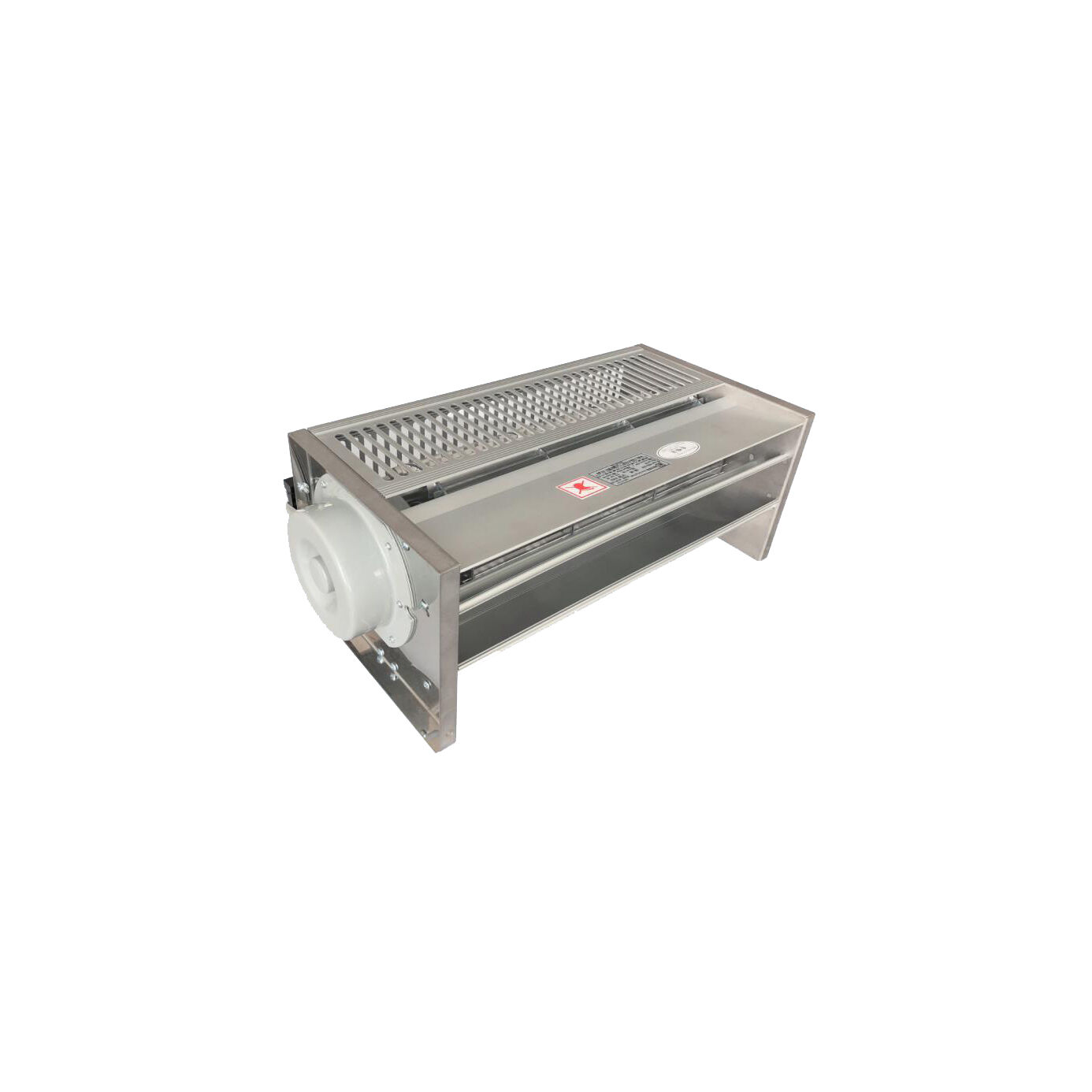
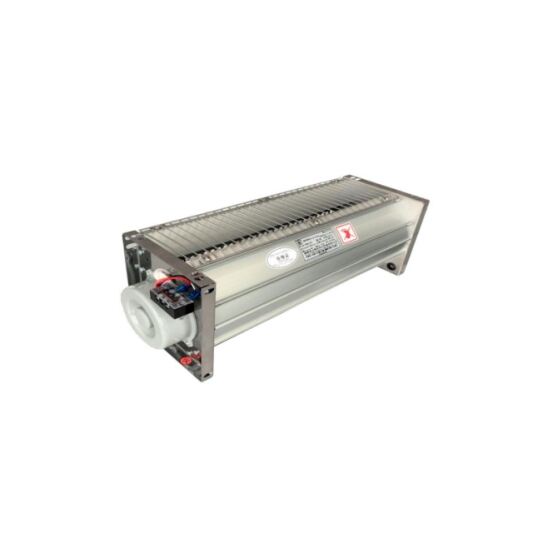
Cross-flow fans, also known as tangential fans, operate on a unique principle that distinguishes them from traditional axial or centrifugal cooling fan designs. The air enters the fan from one side of the cylindrical impeller, passes through the blade passage, and exits from the opposite side, creating a rectangular airflow pattern rather than a circular one. This transverse flow characteristic enables the cooling fan to generate a wide, uniform air curtain that is ideally suited for cooling the flat surfaces and coil structures typical of dry-type transformers. The impeller consists of multiple forward-curved blades arranged in a cylindrical configuration, which produces a relatively low-pressure, high-volume airflow with minimal turbulence.
The aerodynamic efficiency of cross-flow cooling fan systems in transformer applications derives from their ability to distribute cooling air evenly across extended surface areas. Unlike axial fans that produce concentrated airflow in a circular pattern, cross-flow fans create a laminar flow that follows the contours of transformer windings and core structures. This uniform distribution prevents hot spots and ensures consistent temperature profiles throughout the transformer assembly. The cooling fan design also facilitates parallel installation configurations where multiple units can work together without creating interference patterns or dead zones in the airflow field, which is particularly important in large transformer installations requiring substantial heat dissipation capacity.
Comparative Advantages in Dry-Type Transformer Environments
When comparing cooling fan technologies for dry-type transformer applications, cross-flow fans offer several distinct advantages that align with the specific thermal management requirements of these systems. The rectangular discharge pattern of a cross-flow cooling fan matches the geometric profile of transformer coils more effectively than circular airflow patterns, resulting in higher heat transfer coefficients and more efficient thermal performance. This geometric compatibility reduces the required fan capacity and associated energy consumption while maintaining adequate cooling effectiveness. Additionally, the lower air velocity characteristic of cross-flow fans minimizes dust accumulation and mechanical stress on transformer insulation materials, extending the operational lifespan of both the cooling system and the transformer itself.
The acoustic profile of cross-flow cooling fan systems presents another significant advantage in applications where noise control is important. These fans typically generate broadband noise with lower peak frequencies compared to axial fans operating at equivalent airflow rates. The distributed nature of the airflow also reduces the whistling and turbulent noise commonly associated with high-velocity discharge from axial cooling fan systems. In indoor substations, commercial buildings, and residential areas where acoustic emissions must comply with strict environmental regulations, cross-flow fans provide effective cooling while maintaining acceptable noise levels. The compact form factor and flexible mounting options further enhance their suitability for space-constrained installations where traditional cooling fan configurations may not fit within available clearances.
Identifying Optimal Application Scenarios for Cross-Flow Cooling Fans
Load Characteristics and Thermal Management Requirements
The decision to implement cross-flow cooling fan systems for dry-type transformers should be based on careful analysis of load characteristics and thermal management requirements. Transformers operating in continuous high-load conditions, particularly those experiencing load factors exceeding seventy percent of rated capacity, typically require forced air cooling to maintain winding temperatures within acceptable limits. A properly sized cooling fan system can increase the effective capacity of a dry-type transformer by thirty to fifty percent compared to natural convection cooling alone, enabling smaller and more cost-effective transformer selections for given power requirements. The thermal class rating of the transformer insulation system also influences cooling requirements, with higher temperature class insulations allowing reduced cooling fan capacity but potentially at the cost of shortened service life.
Variable load profiles present specific scenarios where cross-flow cooling fan systems deliver particular value. In applications with significant daily or seasonal load variations, such as commercial buildings or educational facilities, the cooling fan operation can be controlled based on actual load conditions rather than worst-case scenarios. Temperature-sensing controls activate the cooling fan when winding temperatures exceed predetermined thresholds, providing cooling only when needed and reducing energy consumption during light-load periods. This demand-based cooling strategy not only conserves energy but also extends cooling fan service life by minimizing operating hours. The relatively quiet operation of cross-flow fans makes them especially suitable for these intermittent-duty applications where noise during low-load periods might otherwise be objectionable.
Environmental Conditions and Installation Environments
Environmental conditions significantly influence the suitability of cross-flow cooling fan systems for particular transformer installations. In indoor environments with controlled ambient temperatures, cross-flow fans provide reliable thermal management with minimal maintenance requirements. These controlled environments protect the cooling fan from weather-related degradation and contamination, ensuring consistent long-term performance. However, the cooling fan must still accommodate the ambient temperature range within the installation space, as elevated room temperatures directly affect cooling effectiveness and may require uprated fan capacity. Indoor installations in electrical rooms or substations often benefit from the compact profile and quiet operation of cross-flow cooling fan configurations, which integrate seamlessly with architectural constraints and acoustic requirements.
Outdoor and semi-outdoor installations present additional considerations for cooling fan selection and configuration. While cross-flow fans can operate in weather-protected outdoor enclosures, the fan housing and electrical components must incorporate appropriate ingress protection ratings to prevent moisture and particulate intrusion. Outdoor transformers with weather-resistant enclosures often incorporate cooling fan systems with enhanced protection features, including sealed motors, moisture-resistant windings, and corrosion-resistant materials. The cooling fan inlet and discharge openings require protective screening to prevent debris accumulation and animal intrusion while maintaining adequate airflow capacity. In coastal or industrial environments with corrosive atmospheric conditions, the cooling fan construction materials and protective coatings become critical factors in achieving reliable long-term operation without premature degradation or performance loss.
Capacity and Power Rating Considerations
The power rating and physical size of dry-type transformers directly correlate with cooling fan requirements and system configuration. Smaller transformers, typically below five hundred kilovolt-amperes, may operate adequately with natural convection cooling under normal load conditions, requiring forced air cooling fan systems only for short-duration overload scenarios or elevated ambient temperature environments. Medium-capacity transformers ranging from five hundred to three thousand kilovolt-amperes commonly incorporate integral cooling fan systems as standard equipment, with the cooling fan capacity selected to enable rated operation at maximum ambient temperature conditions. These installations typically employ multiple cross-flow cooling fan units arranged in parallel to provide both adequate airflow capacity and operational redundancy in case of individual fan failure.
Large dry-type transformers exceeding three thousand kilovolt-amperes invariably require substantial forced-air cooling fan systems to achieve rated capacity. These installations often incorporate sophisticated cooling fan control systems with multiple operating stages that activate additional cooling fan capacity as transformer loading and temperature increase. The staged activation strategy optimizes energy efficiency by operating only the minimum cooling fan capacity needed for current load conditions while maintaining reserve capacity for peak demand periods. Cross-flow cooling fan arrays in these large installations may include six or more individual fan units, with control logic that ensures even distribution of operating hours across all units to equalize wear and maximize system reliability. The redundant capacity also permits continued transformer operation at reduced load levels even if one or more cooling fan units experience failure, providing operational flexibility during maintenance or equipment replacement activities.
Critical Installation Parameters and Configuration Requirements
Airflow Path Design and Clearance Requirements
Proper airflow path design constitutes one of the most critical installation considerations for cross-flow cooling fan systems. The cooling fan must be positioned to direct airflow across the transformer core and winding assemblies in a manner that maximizes heat transfer while minimizing pressure losses and flow recirculation. Adequate clearance between the cooling fan discharge and the transformer surfaces ensures the airflow expands to cover the full cooling surface area rather than creating high-velocity jets that waste energy and create localized turbulence. Industry standards typically recommend minimum clearances of one hundred to two hundred millimeters between the cooling fan discharge and transformer surfaces, though specific requirements vary based on fan capacity and transformer geometry.
The inlet conditions for the cooling fan significantly affect performance and efficiency. Unrestricted inlet airflow allows the cooling fan to operate at design conditions, achieving rated airflow with minimum energy consumption and acoustic emissions. Inlet obstructions, such as closely positioned walls, equipment, or cable trays, create pressure losses that reduce actual airflow below design values and may cause the cooling fan to operate in unstable flow regimes with increased noise and vibration. Installation guidelines specify minimum clearances around cooling fan inlets, typically requiring open space equivalent to at least one times the inlet dimension in all directions. In space-constrained installations where adequate clearances cannot be maintained, inlet guide vanes or expansion plenums may be necessary to condition the airflow and prevent performance degradation.
Mounting Configuration and Structural Considerations
The mounting configuration of cross-flow cooling fan systems must address both functional performance requirements and structural integrity considerations. Most transformer cooling fan installations employ bottom-mounted configurations where fans are positioned beneath the transformer and direct airflow upward through the coil assemblies, leveraging natural convection to enhance overall cooling effectiveness. This vertical airflow arrangement creates a chimney effect that supplements the forced airflow, improving thermal performance while reducing the required cooling fan capacity. Alternative mounting positions, including side-mounted and top-mounted configurations, may be necessary in specific installations due to space constraints or transformer design features, though these arrangements typically require careful attention to airflow management to achieve equivalent cooling effectiveness.
Structural mounting provisions must accommodate the static weight of the cooling fan assembly and the dynamic forces generated during operation. Vibration isolation mounting systems are frequently employed to prevent transmission of cooling fan vibration to the transformer structure and surrounding building elements. These isolation systems typically incorporate elastomeric or spring-type isolators that attenuate vibration across the operating frequency range while maintaining adequate structural rigidity. The mounting structure must also facilitate cooling fan removal and replacement for maintenance activities without requiring transformer de-energization or relocation. Access panels and sufficient working clearances around the cooling fan installation enable routine inspection and service activities, reducing maintenance labor requirements and minimizing transformer downtime during cooling fan replacement procedures.
Electrical Integration and Control System Implementation
Electrical integration of cross-flow cooling fan systems requires careful coordination with transformer protection schemes and facility power distribution infrastructure. The cooling fan power supply must incorporate appropriate overcurrent protection and disconnecting means that comply with electrical code requirements while ensuring reliable cooling fan operation under all necessary conditions. Independent power feeds for cooling fan systems are generally preferred over connections to transformer secondary terminals, as this configuration ensures cooling fan operation during transformer maintenance and provides more straightforward coordination with building electrical systems. The cooling fan electrical specifications, including voltage rating, phase configuration, and power consumption, must align with available facility power to avoid supply incompatibilities that could compromise cooling effectiveness or create installation complications.
Control system implementation significantly influences the operational effectiveness and energy efficiency of cooling fan installations. Basic control schemes employ temperature-sensing thermostats mounted on transformer windings or core structures that activate the cooling fan when temperatures exceed predetermined setpoints. More sophisticated control systems incorporate programmable logic controllers that implement staged cooling fan activation based on multiple temperature sensors and load monitoring inputs. These advanced controls optimize cooling fan operation by activating only the capacity needed for current thermal conditions, reducing energy consumption and extending cooling fan service life. Remote monitoring capabilities enable facility personnel to track cooling fan operation, identify performance anomalies, and schedule preventive maintenance based on actual operating conditions rather than fixed time intervals. Integration with building automation systems further enhances operational visibility and enables coordinated control strategies that optimize facility-wide energy management.
Installation Best Practices and Commissioning Procedures
Pre-Installation Verification and Site Preparation
Thorough pre-installation verification and site preparation activities establish the foundation for successful cooling fan system implementation. Review of installation drawings and specifications confirms that the selected cooling fan model matches design requirements and is compatible with the specific transformer configuration. Verification of site conditions, including available clearances, structural support adequacy, and electrical power availability, identifies potential installation obstacles before equipment arrival on site. Physical inspection of delivered cooling fan equipment checks for shipping damage and confirms that all mounting hardware, electrical components, and installation accessories are present and undamaged. This systematic verification process prevents installation delays and ensures that all necessary resources are available when installation work commences.
Site preparation activities create the physical conditions necessary for efficient installation execution. Installation of structural mounting supports proceeds according to design drawings, with careful attention to dimensional accuracy and structural integrity. Verification of mounting surface levelness and alignment ensures proper cooling fan positioning and prevents operational vibration or performance issues. Preparation of electrical conduit and wiring routes from the power source to the cooling fan location facilitates efficient electrical installation and maintains required separation from transformer components. In renovation projects involving cooling fan additions to existing transformers, site preparation may include removal of obstructions, modification of enclosures to accommodate cooling fan installation, and temporary rigging provisions to facilitate cooling fan positioning without disturbing transformer alignment or connections.
Assembly and Installation Execution
The physical assembly and installation of cross-flow cooling fan systems requires systematic execution following manufacturer instructions and industry best practices. Positioning of the cooling fan assembly on prepared mounting supports confirms proper alignment with the transformer geometry and airflow path design. Installation of vibration isolation mounting components occurs according to manufacturer specifications, ensuring correct compression settings and alignment that will effectively attenuate operational vibration. Securing of mounting fasteners follows prescribed torque values to achieve adequate structural connection without over-stressing mounting components or isolation elements. Verification of cooling fan position relative to transformer surfaces confirms that design clearances are maintained and airflow paths remain unobstructed.
Electrical installation activities connect the cooling fan to the designated power source and control system in accordance with electrical code requirements and manufacturer specifications. Installation of overcurrent protection devices sized according to cooling fan full-load current provides necessary circuit protection while allowing reliable cooling fan starting and operation. Routing and termination of control wiring connects temperature sensors, control relays, and monitoring devices according to control system design. Verification of electrical connections through continuity testing and insulation resistance measurement confirms proper installation before energization. Ground connection installation and verification ensures personnel safety and proper operation of electrical protection systems. Systematic documentation of all installation activities, including photographs of completed work and records of any field modifications, creates valuable reference information for future maintenance and troubleshooting activities.
Commissioning Testing and Performance Verification
Comprehensive commissioning testing verifies that the installed cooling fan system operates correctly and achieves design performance objectives. Initial energization testing confirms proper cooling fan rotation direction, which is critical for achieving design airflow and preventing potential equipment damage. Measurement of cooling fan electrical parameters, including voltage, current, and power consumption, verifies that values fall within expected ranges and indicates proper electrical system operation. Operational testing of control systems confirms that temperature sensing, setpoint adjustment, and cooling fan activation occur as designed. Testing of safety interlocks and alarm functions verifies that protective systems operate correctly and will provide appropriate warnings or protective actions in response to abnormal conditions.
Performance verification activities measure actual cooling fan effectiveness and confirm that thermal management objectives are achieved. Temperature measurement at multiple locations on the transformer during operation with and without cooling fan activation quantifies the cooling effectiveness and verifies achievement of design temperature limits. Airflow measurement using anemometer or pitot tube techniques confirms that actual airflow approximates design values and identifies potential flow restrictions or recirculation problems. Acoustic measurement verifies that noise emissions comply with applicable limits and do not create unacceptable environmental impacts. Documentation of all commissioning results creates baseline performance data that supports future troubleshooting activities and enables trending analysis to identify gradual performance degradation. Final system acceptance occurs only after all commissioning tests demonstrate satisfactory performance and any identified deficiencies have been corrected and retested.
Operational Optimization and Maintenance Strategies
Performance Monitoring and Operational Adjustments
Effective performance monitoring enables proactive identification of cooling fan system issues before they impact transformer operation or reliability. Regular temperature monitoring during various load conditions confirms that the cooling fan system maintains transformer temperatures within acceptable limits across the full operating range. Trending of temperature data over time identifies gradual performance degradation that may indicate cooling fan wear, airflow obstruction, or changing environmental conditions. Monitoring of cooling fan operating hours supports scheduled maintenance planning and replacement part procurement. Advanced monitoring systems with remote data access enable facility personnel to track cooling fan performance continuously without requiring physical site visits, improving operational visibility while reducing inspection labor requirements.
Operational adjustments optimize cooling fan system performance for changing conditions and requirements. Control setpoint adjustments in response to seasonal temperature variations or load pattern changes ensure adequate cooling while minimizing unnecessary cooling fan operation. Staged activation timing adjustments balance cooling effectiveness with energy consumption based on actual operational experience. In installations with multiple cooling fan units, load-balancing strategies that rotate primary and backup units equalize operating hours and component wear, maximizing overall system reliability. Documentation of operational adjustments and the conditions that prompted them creates institutional knowledge that informs future operating decisions and supports continuous improvement of cooling fan system management practices.
Preventive Maintenance Requirements and Schedules
Systematic preventive maintenance preserves cooling fan performance and prevents premature equipment failure. Visual inspection activities check for physical damage, corrosion, loose mounting hardware, and signs of abnormal operation such as excessive vibration or unusual noise. Cleaning of cooling fan components removes accumulated dust and debris that can restrict airflow and reduce cooling effectiveness. Inspection and lubrication of fan motor bearings according to manufacturer recommendations prevents premature bearing failure and extends motor service life. Electrical connection inspection identifies loose terminals or corroded connections that could cause operational problems or safety hazards. These routine maintenance activities typically occur on quarterly or semi-annual schedules depending on environmental conditions and equipment criticality.
Periodic comprehensive maintenance procedures supplement routine inspection and servicing activities. Annual detailed inspection disassembles cooling fan components to examine internal conditions and identify wear that may not be apparent during external inspection. Measurement of cooling fan electrical parameters identifies gradual changes that may indicate developing problems with motors or electrical components. Vibration analysis detects bearing wear or imbalance conditions before they cause component failure. Performance testing under controlled conditions verifies that airflow capacity remains within acceptable ranges and identifies any degradation requiring corrective action. Replacement of aging or degraded components during scheduled maintenance prevents unexpected failures that could compromise transformer cooling and operational reliability. Comprehensive documentation of all maintenance activities creates maintenance history records that support long-term asset management and lifecycle cost analysis.
FAQ
What ambient temperature conditions require forced-air cooling fan systems for dry-type transformers?
Forced-air cooling fan systems become necessary when ambient temperatures exceed thirty degrees Celsius for transformers rated for standard temperature rise, or when operating transformers at loads exceeding their natural convection cooling capacity. The specific threshold depends on transformer temperature class, load duty cycle, and altitude. Transformers installed in enclosed spaces without adequate natural ventilation typically require cooling fan systems regardless of rated ambient temperature. Additionally, installations at elevations exceeding one thousand meters may require cooling fan systems or capacity derating due to reduced air density affecting convection cooling effectiveness. Consulting transformer nameplate ratings and manufacturer recommendations provides specific guidance for particular equipment and installation conditions.
How do you determine the required airflow capacity for a transformer cooling fan system?
Airflow capacity requirements are calculated based on transformer losses, desired temperature rise, and ambient conditions using heat transfer principles. A general approximation requires approximately three to four cubic meters per minute of airflow for each kilowatt of transformer loss at standard conditions. More precise calculations consider the specific heat of air, allowable temperature rise, and heat transfer coefficients for the particular transformer geometry. Manufacturer specifications typically provide required cooling fan capacity for specific transformer models and loading conditions. For retrofit applications or custom installations, thermal modeling or empirical testing may be necessary to determine adequate cooling fan capacity. Professional consultation with cooling system specialists ensures proper capacity selection that balances cooling effectiveness with energy efficiency and acoustic performance.
What are common causes of cooling fan system failures in transformer applications?
Common cooling fan system failures include bearing degradation from inadequate lubrication or contamination, motor winding failures from electrical stress or thermal overload, and control system malfunctions from component aging or environmental exposure. Airflow restriction from accumulated debris or damaged fan blades reduces cooling effectiveness even when the cooling fan motor continues operating. Electrical connection failures from corrosion or mechanical stress can interrupt cooling fan operation unexpectedly. Vibration from mounting system degradation or fan imbalance accelerates wear and may cause secondary damage to nearby components. Regular preventive maintenance, proper installation practices, and appropriate environmental protection significantly reduce failure frequency and extend cooling fan service life. Redundant cooling fan configurations in critical applications provide continued operation during individual fan failures.
Can cross-flow cooling fans be retrofitted to existing dry-type transformers originally designed for natural convection cooling?
Retrofit installation of cross-flow cooling fan systems on existing transformers is technically feasible and commonly performed to increase capacity or accommodate changed operating conditions. The retrofit process requires evaluation of available mounting space, structural support adequacy, electrical power availability, and compatibility with existing transformer enclosures. Transformer manufacturers often provide retrofit cooling fan kits designed specifically for their equipment models, simplifying installation and ensuring proper integration. Custom retrofit installations require careful design to achieve proper airflow distribution and integration with transformer geometry. Verification that added cooling fan capacity enables the desired load increase without exceeding transformer design limits is essential. Professional engineering evaluation ensures that retrofit cooling fan installations achieve intended performance improvements without creating new operational problems or safety concerns.
Table of Contents
- Understanding Cross-Flow Fan Technology in Transformer Cooling Applications
- Identifying Optimal Application Scenarios for Cross-Flow Cooling Fans
- Critical Installation Parameters and Configuration Requirements
- Installation Best Practices and Commissioning Procedures
- Operational Optimization and Maintenance Strategies
-
FAQ
- What ambient temperature conditions require forced-air cooling fan systems for dry-type transformers?
- How do you determine the required airflow capacity for a transformer cooling fan system?
- What are common causes of cooling fan system failures in transformer applications?
- Can cross-flow cooling fans be retrofitted to existing dry-type transformers originally designed for natural convection cooling?